PRINCIPLES FOR THE DESIGN OF MANUALS : A N foundation for PAC is - - PDF document

principles for the design of manuals a n foundation for
SMART_READER_LITE
LIVE PREVIEW

PRINCIPLES FOR THE DESIGN OF MANUALS : A N foundation for PAC is - - PDF document

PRINCIPLES FOR THE DESIGN OF MANUALS : A N foundation for PAC is the distinction promoted b y some theoretical models between the semantic an d EMPIRICAL STUDY AND PRODUCTION RUL E the lexical aspects of the human-compute r ANALYSI S


slide-1
SLIDE 1

PRINCIPLES FOR THE DESIGN OF MANUALS : AN EMPIRICAL STUDY AND PRODUCTION RUL E ANALYSI S

RICHARD CATRAMBON E

Research on manual design often does not speak to th e needs of manual writers . One reason for this state of affairs is that researchers typically do not explain why a principle works or how to implement it in variou s

  • contexts. They do not provide a cognitive model to

justify the principles. A model of how people acquire procedural skills would enable writers to appl y documentation principles more effectively in a variety of

  • contexts. Unfortunately, research that could provide usefu l

models tends not to use realistic tasks . Thus, it is not clear that the tested principles would work for a rea l

  • manual. The goal of the proposed research is to us e

realistic tasks to examine individual principles for manual

  • design. In addition, a production rule formalism based o n

a model of the user's cognition will be used to generate predictions about the success of the documentation produced according to various principles . An example of such a prediction would be : instructions which translate to fewer productions and which require the user to do les s inferencing (i.e., creating new productions from old ones)

will be easier to follow. If the predictions are accurate

then the formalism can be used as an additional tool fo r evaluating documentation principles and guiding their implementation . Richard Catrambone Richard Catrambone is a graduate student in Experimental Psychology at the University of Michigan . His interests include problem solving and the design of documentation . The abstract above is based on his proposed dissertation . Richard's address is: University of Michigan, Departmen t

  • f Psychology, Human Performance Center, 330 Packard,

Ann Arbor, MI 48104 . PAC: AN OBJECT ORIENTED MODEL FOR IMPLEMENTING USER INTERFACE S

JOELLE COUTA Z

  • 1. Introduction

PAC is an implementation model that attempt s to bridge the gap between the abstract sphere of theoretical models such as GOMS [Card 83], and the practical affairs of building user interfaces . The foundation for PAC is the distinction promoted b y some theoretical models between the semantic and the lexical aspects of the human-computer interaction [Foley 82, Norman 84, Shneiderman 87]. However, PAC stresses the fact that thes e notions do not form strict monolithic layers bu t instead, are distributed across various levels of abstraction . This article describes PAC and illustrates its application through a couple of examples . The next section concerns the definition of the mode l per se. Section 3 concentrates on the interest of PAC and shows how this model can provide the foundations for supporting some of the elements essential to the quality of a user interface: context, concurrency and adaptability .

  • 2. PAC, an Implementation Mode l

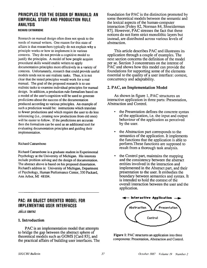
As shown in figure 1, PAC structures a n interactive application in three parts : Presentation , Abstraction and Control.

  • the Presentation defines the concrete synta x
  • f the application, i.e. the input and output

behaviour of the application as perceive d by the user.

  • the Abstraction part corresponds to the

semantics of the application . It implements the functions that the application is able to perform.These functions are supposed to result from a thorough task analysis . the Control part, maintains the mapping and the consistency between the abstrac t entities involved in the interaction and implemented in the Abstract part, and their presentation to the user. It embodies the boundary between semantics and syntax. It is intended to hold the context of th e

  • verall interaction between the user and the

application .

. — Interactive Application

Figure 1: PAC structures an application into thre e components: Presentation, Abstraction and Control .

SIGCHI Bulletin

  • 37
  • October 1987 Volume 19 Number 2
slide-2
SLIDE 2

This constitutes a first level of description of an interactive application. We need now to refine the Presentation part . The Presentation of an application is made of a set of entities called interactive objects. As for applications, an interactive object is organized according to the PAC model: it has a Presentation , an Abstraction and a Control part. An interactive

  • bject may be elementary or may result from the

composition of other PAC entities. There is no restriction on the granularity of a PAC entity. Consider for example the object pipe represented in figure 2 .

Pi pe

Figure 2: a Pipe object structured as a PAC entity and composed of two PAC sub-objects : a gauge and a pipe-element .

The object pipe is supposed to be a component

  • f the Presentation of an application whose

Abstract part would be, for example, the simulator

  • f a plant. The user of the simulator would be

interested in having a global view of the behavio r

  • f the pipe as well as, in certain circumstances,
  • btaining detailed information about a particula r

section of the pipe . The simulator would generate numerical values corresponding to an abstract representation of the pipe (say a Pascal record) an d pass this information to the Control of the

  • application. The Control, which maintains the

mapping between abstract application-dependent entities and presentation user-dependent interactive

  • bjects, would translate the information produce d

by the simulator into the appropriate messages fo r the interactive pipe object . The Abstract part of the pipe is comprised o f numerical values (e.g. pressure, temperature, size , type of the fluid) that can be accessed by the Control of the application through invocation o f the appropriate methods. The Control of the pipe signals changes to the pipe Presentation and, if necessary, to its subobjects. The subobjects of the pipe will be discussed further. For now, let' s carry on with the description of the pipe level . For output, the pipe Presentation i s responsible for drawing the shape of a pipe (i .e a rectangular area of some size, a set o f subrectangular areas of some size, a bend at some location and some colors). The pipe Presentatio n does not know anything about pipes and fluids . For output, it is simply concerned with drawing a picture according to some parameters set by the pipe Control. For example, if the fluid is col d water, the Pipe Control would set the .value of the parameter color of the Presentation to blue and would switch progressively to red as the simulato r would signal heat increase . For input, the Presentation would accep t mouse clicks. For example, the user would click at some place in the picture of the pipe . This click would be interpreted by the pipe Presentation as a "show me the subrectangular area denoted by m y click". The feedback provided by the pipe Presentation would be something like a reverse video of the subarea. Now, if the user "double-clicks" a subarea, the Presentation would perform the same feedback but, in addition, woul d notify the pipe Control that "this subarea has been selected". This event would be interpreted by the pipe Control as a "show me more details about this section" and the user would get a zoom of the

  • section. Let's see how.

As shown in figure 2, the interactive object pipe has subobjects: a set of pipe-elements and a

  • gauge. A pipe-element describes in detail what i s

currently happening in a particular section of the

  • pipe. The Abstraction of the gauge is an integer

value set within a given range; for output, its Presentation is mainly in charge of drawing a needle and a circle of a given size at some location ; for input, it interprets mouse events related to th e needle as modifications of the abstract value . Both the gauge and the pipe-elements are supervised by the Control of the pipe who decide s which abstract information they present. Thus, when the Control of the pipe receives the reques t "show me more details about this section", it generally creates an instance of the clas s pipe-element, sends it the appropriate abstrac t values and asks it to show itself. If the pipe element already exists, but is not currently

SIGCHI Bulletin

  • 38
  • October 1987 Volume 19 Number 2
slide-3
SLIDE 3

displayed, the pipe Control updates the abstrac t values of the pipe-element and asks it to show

  • itself. In addition, when the simulator signal s

temperature modifications, the pipe Control, who maintains the mapping between its temperature abstract value and the gauge, translates temperature modifications into a value that th e gauge Control can understand (according to the gauge Abstract interface). The gauge Control propagates the modification to the gauge

  • Presentation. In addition, the pipe Control know s

that a temperature modification is of interest to the pipe-elements. Therefore, it signals temperature modifications to all of its pipe-elements that are currently displayed and only to those elements . This example shows how semantics and syntax can be distributed at various levels of

  • abstractions. As a result, the simulator does not

need to handle syntactic tasks or low-level semantic tasks which are delegated to some interactive objects. For example, the selection of a pipe element is a syntactic action that is processed at the level of the presentation of the pipe . Similarly, the user's switch of attention to a particular pipe element is a low-level semantic task which is entirely handled by the interactive objec t pipe and its subcomponents . In summary, by applying PAC recursively a t every level of abstraction of the user interface , everything is PAC-ly structured: from the elementary interactive object to the whole

  • application. Moreover, the user interface of a

workstation (generally refered to as a shell) ma y be modelled in a straightforward manner by adding an extra PAC layer on top of th e application level (see figure 3). The Abstract part

  • f this layer may include global data structure s

such as the "clipboard", which are of general interest to the overall interaction . The Presentation would present these data structures and allow for the initial invocation of applications . Finally, the Control part would, of course, bridge the gap between the abstract and the concrete sides . It would as well supervise the control parts of all o f the active applications. Such an arbitrator should provide the basis for a uniform mechanism for transferring data between applications . This recursive object-oriented organization presents some advantages which are described in the following section .

r— Workstation's Shell —or

Figure 3 : The PAC model can be applied recursively at

every level of Abstraction of the workstation environment .

  • 3. The Interest of PAC

The interest of the PAC model is three-fold : it provides the implementer with a consisten t framework, it takes full advantage of the notion of

  • bject and it explicitly introduces the notion of

control.

3.1 . A consistent Framework

PAC defines a framework for th e construction of user interfaces that is applicable in a consistent way at any level of abstraction. As a result, semantics and syntax are distributed acros s a variety of entities rather than forming hermetic layers that do not match the cognitive organization

  • f human knowledge [Anderson 83]. This

distribution, combined to the notion of object an d control, opens the way to more flexible user interfaces. 3.2. The notion of Interactive Objec t Object-oriented programming support data abstraction which makes it possible to change underlying implementations without changing the calling programs. In the case of interest, this principle allows th e internal modification of an interactive object without changing its presentation or its abstrac t

Interactive Applications Interactive Applications

1?i9 e'9 (a:9

Q9 29Q9

SIGCHI Bulletin

  • 39
  • October 1987

Volume 19 Number 2

slide-4
SLIDE 4
  • interfaces. Interestingly, it also permits th e

modification of one interface without any side-effect on the other one. For example, one can modify the presentation of an interactive objec t without reflecting on its abstract behaviour. This property makes it possible fine grained explici t adjustments of the user interface without questioning the presentation of the whole application. A second type of customization is th e automatic adaptation to the user. The object paradigm seems suitable for the implementation of a distributed intelligent observer where each interactive object would model the user with it s

  • wn set of rules as is provided by Loops [Bobrow

81] . This view of the user would be maintained

locally by the Control part of each interactive

  • bject .

3.3 . The Notion of Control

Generally speaking, the Control is a link between semantics and syntax . This link is mandatory since even minor syntactic details require knowledge about the semantics. The role

  • f the control part is thus to maintain an extensive

knowledge about the two worlds it serves . As shown in figure 4, this knowledge can include contextual information that may be useful for automatic adaptation to the user, history, help , error explanation and multi-thread dialogue .

Error

  • Multi-thread

explanation ,— Context

  • dialogue

History

  • Help

Customization

Figure 4: Contextual information that a Control part ma y hold.

To illustrate how the notion of Control may be exploited for supporting history, let us take the example of a string object used as a field in som e

  • form. The Control of the string may keep track o f

the values that the user has successively entere d during the session . The user would then be able to retrieve the various values of the field by issuin g the "next" or "previous" commands (for example , by typing Ctrl-n or Ctrl-p, if an Emacs-lik e key-translation-table is attached to the string) or b y selecting the values through a pop-up men u attached to the string . Multi-thread dialogue may be provided by means of a set of finite state machines localized in the Control part of interactive objects . By doing so, each object is able to maintain its own stat e with regard to the interaction and react to the user's actions according to its current status . Thus, the control of the interaction is not provided by a unique monolithic dialogue handler sittin g between the application and the user; instead, it is distributed at various levels of abstraction acros s entities involved in the interaction . This distributed automaton provides for free the maintenance of the user's arbitrary manipulations. As a second example of the utility of multi-thread dialogue, let's consider the top level

  • Control. For reasons not justified here [Coutaz

86], the top controller holds the main control loop

  • f the dialogue but hooks must be provided for

mixed control . Mixed control is required by applications when data are needed from the user during the processing of a function (e.g. the popular Unix "more" command) . The problem is that the control must not stay in the applicatio n hands because the user should not be bound t o directly satisfy the request. He should be able to invoke several functions of the application before replying to the initial request. For doing so, the Abstract application issues READ messages and the top controller maintains dialogue state variable s such as request objects . On reception of a READ message, the top controller creates a request objec t and activates the interactive objects that represent the abstract entities referenced in the READ

  • message. The request object watches the

interaction between the user and the interactiv e

  • bjects and detects when the user has satisfied or

cancelled the READ . When the READ operation is completed, control automatically returns to the instruction following the READ in the abstract par t

  • f the application .
  • 4. Conclusion

The notion of object and the distinction between mechanisms and policies are advocated by other models such as Smalltalk's MVC . However, PAC and MVC differ in several ways : PAC combines inputs and outputs into the Presentation whereas MVC separates them into the

SIGCHI Bulletin

  • 40
  • October 1987 Volume 19 Number 2
slide-5
SLIDE 5

Controller and the View. The distribution has the advantage of the flexibility although it is often th e case that input events are strongly coupled t o immediate output feedback. In PAC, control is an explicit central link between mechanisms and policies whereas in MVC, this notion is diluted across related objects which must be careful a t maintaining consistency between themselves . PAC has been used for the construction of a n application framework that provides application programmers with a reusable and extensible skeleton [Coutaz 87] . This skeleton has bee n implemented in C on top of the Macintosh toolbo x and has been re-used for two interactiv e applications : a simple graphics editor and a graphics terminal emulator . PAC is currently bein g applied to the development of MOUSE, an objec t

  • riented User Interface Management System

[Coutaz 86]. References

[Anderson 83] J .R. Anderson: The Architecture of Cognition, Harvard University Press, 1983 . [Bobrow 81] D .G. Bobrow, M. Stefik: The Loops Manual;

  • Tech. report KB-VLSI-81-13, Knowledge Systems Area ,

Xerox, Palo Alto Research Center, 1981 . [Card 83] S. Card, T. Moran, A. Newell: The Psychology

  • f Human-Computer Interaction ; ISBN 0-89859-243-7 ,

Lawrence Erlbaum Associates, Publish ., 1983 . [Coutaz 86] J. Coutaz: The Construction of User Interfaces , IFIP Conference on Methods and Tools for Office Systems , Pisa, October 1986 . [Coutaz 87] J .Coutaz: The Construction of User Interfaces and the Object Paradigm, European Conference on Objec t Oriented Programming, Paris, June, 1987 . [Foley 82] J. Foley, A. Van Dam: Fundamentals of Interactive Computer Graphics, Addison-Wesley Publishing Co., Reading, MA, 1982 . [ Goldberg 84] A. Goldberg, D. Robson: Smalltalk-80 : The Interactive Programming Environment ; Addison-Wesley Publ., 1984 . [Norman 84] D. Norman: Stages and Levels i n Human-Machine Interaction; International of Man-Machine Studies, 21, 1984, 365-375. [Shneiderman 87] B. Shneiderman: Designing User Interface: Strategies for Effective Human-Computer Interaction; Addison-Wesley Publishing Co., Reading, MA, 1987 .

Joelle Coutaz Joelle Coutaz is a professor at the University of Grenoble (France) where she earned a doctorat e degree in Computer Science . Ms. Coutaz ha s spent two years at the Carnegie-Mellon University

  • Dept. of Computer Science as a visiting scientist i n

the Spice and the Gandalf projects. Her research interests include operating systems ,

  • bject-oriented programming, and distribute d
  • software. Since 1982, she has been working on

the development of software tools for the construction of user interfaces .

A USER INTERFACE DESIGN TOO L

DAVID ENGLAN D

  • 1. Introduction .

This paper discusses a user interface design tool for use in the Alvey ECLIPSE project. ECLIPSE is a second - generation integrated project support environment for medium to large software projects . Currently tool user interfaces in ECLIPSE are written in the Format Description Language (FDL) which defines the objects the user sees on the screen and how he/she interacts with

  • them. FDL is interpreted at run time by a user interfac e

management system. However, a language-base d approach makes it difficult to visualise the user interface . A more direct approach is required (especially for the graphical interfaces used in Eclipse) to assist rapi d prototyping and permit more user involvement in design . This paper looks at a tool for the "Direc t Manipulation"[1] of interface objects and th e methodology surrounding the tool . The tool is the centre

  • f a design-prototype-evaluate iterative loop.
  • 2. The User Interface Tool.

The user interface tool allows user interfac e

  • bjects(choice items, command items and so on) to be

manipulated on a bit-mapped screen . This frees the designer from having to specify locational information in

  • FDL. The designer can also edit the attributes of user

interface objects via a form filling interface further reducing the need to know the syntax of FDL. When the designer is satisfied with the layout the tool can be switched to simulation mode to emulate the running

  • system. When the design is finalised the designer can

request the tool to output an FDL description . The tool can also output SunView C code (for non-ECLIPSE tools) and PostScript (for printing). The project database ensures that the designer can only edit an interfac e through the tool, any code output is not editable .

  • 3. A Design Notation

At this point we have a useful tool which allows rapi d prototyping, simulation and avoids learning a layout

SIGCHI Bulletin

  • 41
  • October 1987 Volume 19 Number 2