
SLIDE 1
1
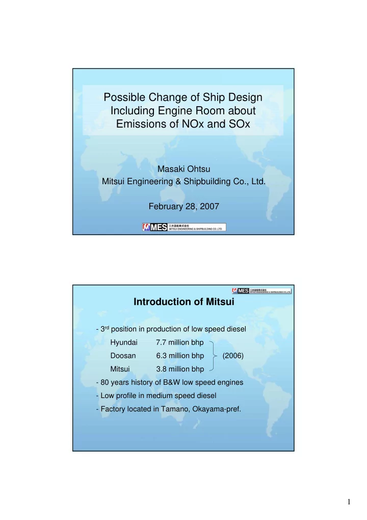
Possible Change of Ship Design Including Engine Room about Emissions of NOx and SOx
Masaki Ohtsu Mitsui Engineering & Shipbuilding Co., Ltd. February 28, 2007
Introduction of Mitsui
- 3rd position in production of low speed diesel
Hyundai 7.7 million bhp Doosan 6.3 million bhp (2006) Mitsui 3.8 million bhp
- 80 years history of B&W low speed engines
- Low profile in medium speed diesel
- Factory located in Tamano, Okayama-pref.