
SLIDE 1
7.2 Ship Drive Train and Power
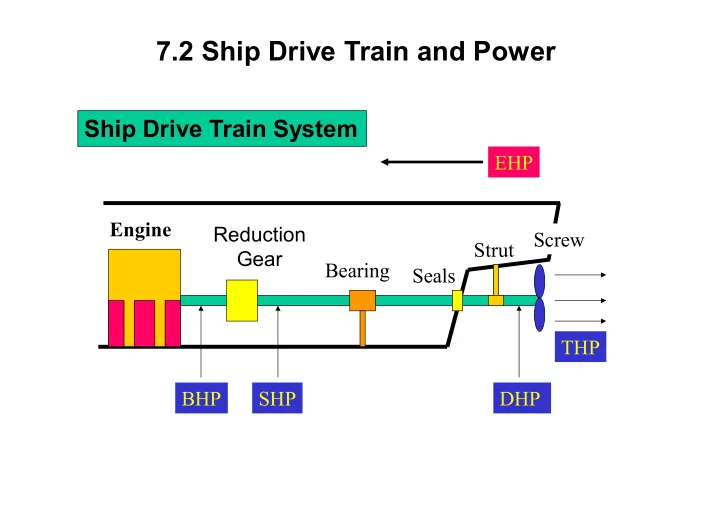
Ship Drive Train System
Engine Reduction Gear Bearing Seals Screw Strut BHP SHP DHP THP EHP
7.2 Ship Drive Train and Power Ship Drive Train System EHP Engine - - PowerPoint PPT Presentation
7.2 Ship Drive Train and Power Ship Drive Train System EHP Engine Reduction Screw Strut Gear Bearing Seals THP BHP SHP DHP Ship Drive Train and Power EHP Engine Strut Reduction Screw Bearing Gear Seals THP BHP DHP SHP
Engine Reduction Gear Bearing Seals Screw Strut BHP SHP DHP THP EHP
Brake Horsepower (BHP)
the reduction gears
Engine
Reduction Gear Bearing Seals Screw Strut SHP DHP THP
BHP
EHP
Shaft Horsepower (SHP)
Engine
Reduction Gear
Bearing Seals Screw Strut
BHP
SHP
DHP THP EHP
Engine Reduction Gear
Bearing Seals
Screw Strut
BHP SHP
DHP
THP EHP
Delivered Horsepower (DHP)
Engine Reduction Gear
Bearing Seals Screw
Strut
BHP SHP DHP
THP
EHP
Thrust Horsepower (THP)
Relative Magnitudes
E/G R/G BHP SHP Shaft Bearing Prop. DHP THP EHP Hull The reverse relationship can NEVER be true because there is ALWAYS some loss of power due to heat, friction, and sound
the various speeds of the model ship
ship by Froude’s Law.
V Towing Tank Towing carriage Measured EHP The power required to move the ship hull at a given speed in the absence of propeller action EHP is not related to Power Train System
200 400 600 800 1000
Effective Horsepower, EHP (HP)
2 4 6 8 10 12 14 16
Ship Speed, Vs (Knots)
POWER CURVE
YARD PATROL CRAFT
Typical EHP Curve of YP
The required EHP varies depending on the vessel’s speed.
EHP Calculation
P S T P
ship
speed V resistance hull total
S
T
R
P S T
H atts Watts s J s ft lb s ft lb V R 550 / 1 W 1 : Power
The loss in HP along the drive train can be related in terms of
the reduction gears
Gear Efficiency
BHP
Shaft Horsepower Brake Horsepower
Shaft Transmission Efficiency
SHP
bearings and seals that support and seal the drive shaft
Delivered Horsepower Shaft Horsepower
Hull Efficiency
THP EHP
H
1
H
1
H
Well-designed Poorly-designed
to get designed speed.
Effective Horsepower Thrust Horsepower (The loss of power will be a function of the hull design)
Screw Propeller Efficiency
propeller
SHP DHP THP EHP
Propulsive Efficiency (Coefficient (PC))
SHP
Effective Horsepower Shaft Horsepower
Example:
Through modeling of a ship’s design, it is found that the towing horsepower required to maintain a speed of 20 knots is 23,500 HP. Assuming a propulsive efficiency of 68%, what is the expected required power output from the reduction gears (shaft horsepower)? Solution: SHP = 34,559 HP
.68 = 23,500 HP SHP
SHP
SHP = 23,500 HP / .68
_HP _HP _HP _HP _HP
hgear=_HP/_HP (~__-__%) hshaft=_HP/_HP (~__-__%) hprop=_HP/_HP (~__-__%) hH=_HP/_HP hP=PC=_HP/_HP (~__-__%)
Prime Mover Reduction Gear Shafting & Bearings Propeller Hull BHP SHP DHP THP EHP
hgear=SHP/BHP (~98-99%) hshaft=DHP/SHP (~97-98%) hprop=THP/DHP (~70-75%) hH=EHP/THP hP=PC=EHP/SHP (~55-75%)
Total Hull Resistance (RT) The force that the ship experiences opposite to the motion of the ship as it moves. EHP Calculation
P S T P
ship
speed V resistance hull total
S
T
R
Coefficient of Total Hull Resistance
2 S
s T T
hull submerged the
area surface wetted ship
Speed density Fluid resistance hull Total water calm in resistance hull total
t Coefficien S V R C
S T T
dimension
lb
2 2 4 2
ft s ft ft s lb
Coefficient of Total Hull Resistance
S T
V S C , , and
T S T
2
S T
Relation of Total Resistance Coefficient and Speed
5000 10000 15000 20000
Total Resistance, Rt (lb)
2 4 6 8 10 12 14 16
Ship Speed, Vs (knots)
TOTAL RESISTANCE CURVE
YARD PATROL CRAFT
speed high at 5
speed low at 2 from
2
n V V C R
n S S T T
speed high at 6 to speed low at 3 from
2
n V V V C V R EHP
n S S S T S T
Resistance values, denoted by R, are dimensional values RT = Total hull resistance is the sum of all resistance
RAA = Resistance caused by calm air on the superstructure RW = Resistance due to waves caused by the ship
Froude number (ship length & speed)
RV = Viscous resistance (frictional resistance of water)
area of ship
For pilots, this is subsonic, incompressible drag
Viscous Resistance Wave Making Resistance Air Resistance
Total Resistance and Relative Magnitude of Components Viscous Air Resistance Wave-making Speed (kts)
Hump Hollow
Viscous Resistance
( due to friction of the water against the surface of the ship)
generally affect the viscous resistance. Wave-Making Resistance
displacement, shape of hull, Froude number (ship length & speed) Air Resistance
wind present
above the water line, wind velocity and direction
CT = Coefficient of total hull resistance
CV = Coefficient of viscous resistance over the wetted area of the ship as it moves through the water
= Tangential component (skin resistance)
CW = Coefficient of wave-making resistance
Viscous Flow around a ship Real ship : Turbulent flow exists near the bow. Model ship : Studs or sand strips are attached at the bow to create the turbulent flow.
Coefficients of Viscous Resistance
CF=tangential (skin friction) component of viscous resistance KCF=normal (viscous pressure/form drag) component of viscous friction
F F
normal tangential V
Tangential Component : CF
a net force opposing the motion ; Skin Friction
data of flat plate.
F
C flow ship bow stern
S n n F F V
2 10
Semi-empirical equation
water salt for water fresh for /s ft 10 1.2791 /s ft 10 1.2260 /s) (ft Viscosity Kinematic ) Speed(ft/s Ship (ft) L Number Reynolds
2 5
5
pp
S n
V L R
Bernoulli’s Equation: p/r+V²/2+gz=constant
High Velocity/ Low Pressure Low Velocity/ High Pressure Low Velocity/ High Pressure Turbulent Wake Boundary Layer Boundary Layer Separation High Velocity/ Low Pressure Low Velocity/ High Pressure
Tangential Component: CF
· Laminar flow : In laminar flow, the fluid flows in layers in an orderly fashion. The layers do not mix transversely but slide over one another. · Turbulent flow : In turbulent flow, the flow is chaotic and mixed transversely. Laminar Flow Turbulent Flow Flow over flat plate
5
5
Normal Component: KCF
underwater hull form of ship
the motion and a lower pressure is formed aft.
Fuller shape ship has larger normal component than slender ship. Full ship Slender ship large eddy small eddy
Normal Component: KCF
2 3
F F v
2 3
2 10
n F
water salt for water fresh for /s ft 10 1.2791 /s ft 10 1.2260 /s) (ft Viscosity Kinematic ) Speed(ft/s Ship (ft) L Number Reynolds
2 5
5
pp
S n S n
V L R LV R
K= Form Factor
Reducing the Viscous Resistance Coeff.
Increase L while keeping the submerged volume constant 1) Form Factor K Normal component KCF Slender hull is favorable. ( Slender hull form will create a smaller pressure difference between bow and stern.) 2) Reynolds No. Rn CF KCF
The Froude Number (inertia force/gravity force) is another dimensionless value derived from model testing:
Also used, but not dimensionless, is the Speed-to-Length Ratio: Speed-to-Length Ratio = V
...Velocity is typically expressed in Knots (1 knot = 1.688ft/s)
Typical Wave Patterns are made up of TRANSVERSE and DIVERGENT waves Transverse wave Stern divergent wave Bow divergent wave Bow divergent wave
Wave Length
L
because the wave lengths are smaller than the ship length.
increases.
the wave making resistance increases very rapidly. This is the main reason for the dramatic increase in Total Resistance as speed increases.
Wave Length Wave Length Slow Speed High Speed Vs < Hull Speed Vs Hull Speed Hull Speed : speed at which the transverse wave length equals the ship length. (Wavemaking resistance drastically increases above hull speed)
Hump on the resistance curve. Hump : When the bow and stern waves are in phase, the crests are added up so that larger divergent wave systems are generated. Hollow : When the bow and stern waves are out of phase, the crests matches the trough so that smaller divergent wave systems are generated.
Viscous Air Resistance Wave-making Speed (kts)
Hump Hollow
from any theoretical or empirical equation. (Because mathematical modeling of the flow around ship is very complex since there exists fluid-air boundary, wave-body interaction)
are needed to calculate the Cw of the real ship.
It takes energy to produce waves, and as speed increases, the energy required is a square function of velocity!
The limiting speed, or hull speed, can be found as:
Note: Remember at the hull speed, Lwave and Ls are approximately equal!
1) Increasing ship length to reduce the transverse wave
ship will be small until the ship reaches to the hull speed.
FFG7 : ship length 408 ft hull speed 27 KTS CVN65 : ship length 1040 ft hull speed 43 KTS
2) Attaching Bulbous Bow to reduce the bow divergent wave
ideally no waves, practically smaller bow divergent waves.
DDG 51 : 7 % reduction in fuel consumption at cruise speed 3% reduction at max speed. design &retrofit cost : less than $30 million life cycle fuel cost saving for all the ship : $250 mil. Tankers & Containers : adopting the Bulbous bow
Allowance n Correlatio 1 : C C C K) ( C C C C C
A A W F A W V T
paint roughness, corrosion, and fouling of the hull surface.
from model test results.
. smooth is surface model Since
A
C
Appendage Resistance
such as rudder, propeller shaft, bilge keels and struts
Steering Resistance
Added Resistance
motions (pitching, rolling, heaving, yawing).
Increased Resistance in Shallow Water
Increases frictional resistance
the ship than they do in deep water for the same speed. Increases wave making resistance
So far we’ve discussed what resistance is and how it can quantified using:
resistance between dissimilar hull shapes and sizes
We can now measure the resistance in a hull and use the data to designing a ship’s power plant
Resistance and power are related!
Resistance can be measured in two ways:
3 dimensions
Tow Tank testing is the obvious way to go! But to do so, your “model” ship must meet some criteria:
…Note that a “minor” error in any length measurement will be cubed (n3)in volume scaling!
l = LS (ft) LM (ft) l2 = SS (ft2) SM (ft2) l3 = VS (ft3) VM (ft3) Length Area Volume
where: M = Model S = Ship
and the forces of gravity can not be manipulated
The Law of Corresponding Speeds says:
We’ve already defined l as: l = LS (ft) LM (ft) If we wanted to solve for the scale speed for the model,
...NOTE! 1 kt is equal to 1.688 ft/sec! ALL velocities are done in feet/sec!
Example 1:
The USS Monitor was 197 ft long and 40 ft across the beam and was able to maintain a maximum speed of 6 kts. You would like to create a model for testing that is 5 ft long. How wide should the model be? How fast should the model be towed to represent the actual ship’s max speed?
l = LS/LM l = 197 ft /5 ft l = 39.4
Solving for the width,
l = WS/WM WM = 40 ft/39.4 WM = 1.015 ft
Solving for the maximum speed,
VM = 6 kts (1.688 ft/sec-kts) x 39.4-1/2 VM = 10.128 ft/s x .1593
Example 2:
The Yard Patrol (YP) is 110 ft long. It has a top speed of 13 kts on a good
How long must a 1:25 scale model be? How fast must it be towed to simulate the top speed?
l = 25 (the scale is given!) 25 = LS/LM LM= 110ft/25 LM 4.4 ft (52.8 in)
Solving for the maximum speed,
VM = 13 kts (1.688 ft/sec-kts) x 25-1/2 VM = 21.944 ft/s x .0.20
– D=300LT Length=100ft Beam=25ft Draft=6ft Wetted Surface Area=3225ft² Desired Max Speed=15kts
handle is 5ft. If the model is constructed of this length, to maintain geometric similarity, what would be its beam?
surface area of the model?
we need to tow the model?
wave making coefficient (Cw)?
for the full size ship at this speed?
how many SHP are required?
Bm=Bs/l=25ft/20=1.25ft
which is proportional to l³; Dm=Ds/l³=300LT×(2240lb/LT)/20³=84lbs
vm=vs/l½=15kts×(1.688ft/s-kt)/20½=5.7ft/s
s²/ft4×8.06ft²×(5.7ft/s)²]=0.0253; Cw=CT-Cv=0.0253- 0.0064=0.0189
s²/ft4)×3225ft²×(15kt×1.688ft/s-kt)²=45,100lb
kt/(550ft-lb/s-HP)=2076HP; SHP=EHP/hp=2076/0.55=3775HP
HUB ROOT BLADE TIP TIP CIRCLE
ROTATION
LEADING EDGE TRAILING EDGE
PRESSURE FACE SUCTION BACK
PROPELLER DISC
It usually varies from root to tip.
the blade tip.
Hub
pitch The distance that the blade travels in one revolution, P
The pitch angle relates the pitch length to the
… Pitch angle f is the angle that any part of the blade makes perpendicular with the water flow
root as at the tip of the blade, but the pitch will vary or the pitch does not change, but the pitch angle does change. 2. Variable Pitch- The pitch angle changes as the distance from the root changes (f is defined at a blade radius of .7r) 3. Fixed Pitch- The blade is permanently attached to the hub and cannot change. 4. Controllable Pitch- The position of the blade can be altered while the blade rotates, thereby changing the pitch angle.
L.E. T.E. Suction side Pressure side
Forward Propeller Rotation High Pressure Face Suction Back Relative Motion of Water Flow Reaction Force
Propeller Thrust Resistance to Propeller Rotation
Pitch Angle
Left hand screw
Right hand screw
Naval Ship Submarines & torpedoes
Counter Rotating Propellers
the direction of rotation
The Skewed Propeller
Highly Skewed Propeller for a DDG 51
Advantages:
and rudder wake
Disadvantages:
Q P Wake Region
S
V
W
V
water
V
S water
V V
ship with a wake speed (Vw).
W S A
Speed of Advance
Propeller Efficiency
t propeller
C 1 1 2
DHP THP
propeller
(~70 % for well-designed PP.)
T
A V T C
2
5 . 0
Ao (i.e., Diameter ) ; CT
; Prop Eff.
The larger the diameter of propeller, the better the propeller efficiency Maximum
disc propeller projected the
Area : A r thrust Propelle : t coefficien loading Thrust :
CT
Cavitation occurs on propellers that are heavily loaded, or are experiencing a high thrust loading coefficient
pressure has fallen below the vapor pressure of water
Cavitation Process Pressure (atm) Vaporization Line Temperature (°C) LIQUID VAPOR 20 100 1.0 Pv A B C Vapor pressure 15°C 0.25 psi 100°C 14.7psi=1atm =101 kPa
(‘A’ to ‘B’ – boiling water) (‘A’ to ‘C’ – cavitation)
Blade Tip Cavitation Sheet Cavitation Navy Model Propeller 5236 Flow velocities at the tip are fastest so that pressure drop
Large and stable region of cavitation covering the suction face of propeller.
Consequences of Cavitation 1) Low propeller efficiency (Thrust reduction) 2) Propeller erosion (Mechanical erosion) (Severe damage to propeller : up to 180 ton/in²) 3) Vibration due to uneven loading 4) Cavitation noise due to impulsion by the bubble collapse
Preventing Cavitation
an abrupt change in thrust. rapid change of rpm high propeller thrust but small change in VA larger CT cavitation & low propeller efficiency
cavitation as hydrostatic pressure increases.
Ventilation
air or exhaust gases are drawn into the propeller blade due to the localized low pressure around propeller.
exhaust gases into the water causing effects similar to those for cavitation.
draft) and in rough seas.
Direction
Forward
R
Direction
Forward
R