
SLIDE 1
Personal Fall Arrest st Syst ystems
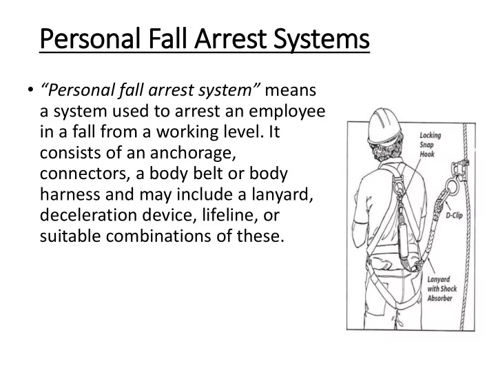
- “Personal fall arrest system” means
Personal Fall Arrest st Syst ystems Personal fall arrest system - - PowerPoint PPT Presentation
Personal Fall Arrest st Syst ystems Personal fall arrest system means a system used to arrest an employee in a fall from a working level. It consists of an anchorage, connectors, a body belt or body harness and may include a
Page 32
(4 kN) when used with a body belt;
pounds (8 kN) when used with a body harness;
than 6 feet (1.8 m), nor contact any lower level;
deceleration distance an employee travels to 3.5 feet (1.07 m); and,
impact energy of an employee free falling a distance of 6 feet (1.8 m), or the free fall distance permitted by the system, whichever is less.
Page 30
Page 31
contact any lower level.
distance to 3½ feet.
worker free falling a distance of 6 feet, or the free fall distance permitted by the system, whichever is less
subjected to fall impact, until inspected by a competent person and deemed undamaged and suitable for use.
to rescue themselves.
and remove defective components from service.
Page 33
Page 35
Page 36
the belt toward you, grasping the belt with your hands six to eight inches apart. Bend the belt in an inverted "U." Watch for frayed edges, broken fibers, pulled stitches, cuts or chemical damage. Check D-rings and D-ring metal wear pads for distortion, cracks, breaks, and rough or sharp edges. The D-ring bar should be at a 90 degree angle with the long axis of the belt and should pivot freely.
unusual wear, frayed or cut fibers, or distortion of the buckles. Rivets should be tight and unremovable with fingers. Body side rivet base and outside rivets should be flat against the material. Bent rivets will fail under stress.
tufts on the webbing surface. Any broken, cut or burnt stitches will be readily seen.
They should overlap the buckle frame and move freely back and forth in their
edges.
must be straight. Pay special attention to corners and attachment points of the center bar. Page 36
the lanyard so that the entire circumference is checked. Spliced ends require particular
keeper or latch should seat into the nose without binding and should not be distorted or
Keeper locks must provide the keeper from opening when the keeper closes.
splice, and the splice should have no loose or cut strands. The edges of the thimble should be free of sharp edges, distortion, or cracks.
patterns on the wire. The use of steel lanyards for fall protection without a shock-absorbing device is not recommended. Do not use steel lanyards in the presence of electrical hazards.
webbed lanyard. This will reveal any cuts or breaks. Due to the limited elasticity of the web lanyard, fall protection without the use of a shock absorber is not recommended.
light any fuzzy, worn, broken or cut fibers. Weakened areas from extreme loads will appear as a noticeable change in original diameter. The rope diameter should be uniform throughout, following a short break-in period. When a rope lanyard is used for fall protection, a shock-absorbing system should be included. Page 37
degrees Fahrenheit.
Transverse cracks appear when belt is bent over tight. This causes a loss of elasticity in the belt.
because ultraviolet rays can reduce the strength of some material.
molten metal or flame. Watch for hard, shiny spots or a hard and brittle feel. Webbing will not support combustion, nylon will.
damage. Page 38
his/her hands free to work. Whenever the worker leans back, the system is activated. However, the personal positioning system is not specifically designed for fall arrest purposes. The only time a body belt may be used where there may be a fall is when an employee is using a "positioning device." In §1926.500
"positioning device system" is defined as a body belt
to be supported on an elevated vertical surface, such as a wall (or a pole), and work with both hands free while leaning. Therefore, in construction work, a positioning device may be used only to protect a worker on a vertical work surface. These devices may permit a fall of up to 2 feet (0.6 m). They may be used in concrete form work, installation of reinforcing steel, and certain telecommunications work. Since construction workers in bucket trucks, scissor lifts and boom-type elevating work platforms are on a horizontal surface, a positioning device may not be used for those workers.
Page 39
A restraint system prevents a worker from being exposed to any fall. If the employee is protected by a restraint system, either a body belt or a harness may be used. When a restraint system is used for fall protection from an aerial lift or a boom-type elevating work platform, the employer must ensure that the lanyard and anchor are arranged so that the employee is not potentially exposed to falling any distance. While fall restraint systems are not mentioned in OSHA’s fall protection rules, OSHA will accept a properly utilized fall restraint system in lieu
restraint system is rigged so that the worker cannot get to the fall hazard. In effect, (if properly used) the system tethers a worker in a manner that will not allow a fall of any distance. A fall restraint system is comprised of a body belt or body harness, an anchorage, connectors, and other necessary equipment. Other components typically include a lanyard, and may also include a lifeline and other devices.
equipment, or employees.
“Cover”.
Page 42
walking/working surface for a distance sufficient to protect employees below.
any downward or outward direction at any point along the toeboard.
walking/working surface. They shall have not more than 1/4 inch (0.6 cm) clearance above the walking/working surface. They shall be solid or have openings not over 1 inch (2.5 cm) in greatest dimension.
shall be erected from the walking/working surface or toeboard to the top of a guardrail system's top rail or midrail, for a distance sufficient to protect employees below.
passage of potential falling objects.
edge.
the work area by removal at regular intervals.
erected at the edge.
penetration by any objects which may fall onto the canopy
Page 44
edge.
which is parallel to the direction of mechanical equipment operation, and not less than 10 feet (3.1 m) from the roof edge which is perpendicular to the direction of mechanical equipment operation.
path formed by two warning lines.
the warning line, shall be placed across the path at the point where the path intersects the warning line erected around the work area, or the path shall be offset such that a person cannot walk directly into the work area.
inches (.9 m) from the walking/working surface and its highest point is no more than 39 inches (1.0 m) from the walking/working surface;
force of at least 16 pounds (71 N) applied horizontally against the stanchion, 30 inches (.8 m) above the walking/working surface, perpendicular to the warning line, and in the direction of the floor, roof, or platform edge;
stanchions, shall be capable of supporting, without breaking, the loads applied to the stanchions as prescribed in paragraph (f)(2)(iii) of this section; and
result in slack being taken up in adjacent sections before the stanchion tips over.
work in that area.
guardrail system, or personal fall arrest system.
Page 46
shall comply with the following provisions:
employer shall ensure that the safety monitor complies with the following requirements:
employee being monitored;
monitoring function.
to monitor employees engaged in roofing operations on low-slope roofs.
covered by a fall protection plan, shall be allowed in an area where an employee is being protected by a safety monitoring system.
warnings from safety monitors.
control line or by any other means that restricts access.
except when erecting precast concrete members.
leading edge.
edge.
related work at the working edge and shall be approximately parallel to the working edge.
surface and its highest point is not more than 45 inches (1.3 m) [50 inches (1.3 m) when overhand bricklaying operations are being performed] from the walking/working surface.
enlarged, as necessary, to enclose all points of access, material handling areas, and storage areas.
place, only that portion of the guardrail necessary to accomplish that day's work shall be removed.
Page 48
30 feet above a lower level where metal decking is initially being installed and forms the leading edge of a work area. In each CDZ, the following shall apply:
more than two stories or 30 feet (9.1 m), whichever is less.
than 90 feet (27.4 m) wide and 90 (27.4 m) feet deep from any leading edge. The CDZ shall be marked by the use of control lines or the equivalent. Examples of acceptable procedures for demarcating CDZ's can be found in Appendix D to this subpart.
1926.761.
control line and shall have at least two attachments for each metal decking panel.
CDZ. Page 49
leading edge work, precast concrete erection work, or residential construction work (See 1926.501(b)(2), (b)(12), and (b)(13)) who can demonstrate that it is infeasible or it creates a greater hazard to use conventional fall protection
specifically for the site where the leading edge work, precast concrete work, or residential construction work is being performed and the plan must be maintained up to date.
maintained at the job site.
conventional fall protection systems (guardrail systems, personal fall arrest systems, or safety nets systems) are infeasible or why their use would create a greater hazard.
will be taken to reduce or eliminate the fall hazard for workers who cannot be provided with protection from the conventional fall protection systems. For example, the employer shall discuss the extent to which scaffolds, ladders, or vehicle mounted work platforms can be used to provide a safer working surface and thereby reduce the hazard of falling.
protection methods cannot be used. These locations shall then be classified as controlled access zones and the employer must comply with the criteria in paragraph (g) of this section.
implement a safety monitoring system in conformance with 1926.502(h).
controlled access zones. No other employees may enter controlled access zones.
(e.g., a near miss) the employer shall investigate the circumstances of the fall or
new practices, procedures, or training) and shall implement those changes to prevent similar types of falls or incidents Pages 50 and 51
its employees are to work have the strength and structural integrity to support the employees safely. Employees must only be allowed to work
Roofs & Roofing Supports
During the course of construction, alteration, or repairs, form and scrap lumber with protruding nails, and all other debris, shall be kept cleared from work areas, passageways, and stairs, in and around buildings or other structures.
Wrong Right
Page 53
support for freshly placed or partially cured concrete, including the mold or sheeting (form) that is in contact with the concrete as well as all supporting members including shores, reshores, hardware, braces, and related hardware.
employee on the face of formwork or reinforcing steel shall be protected from falling 6 feet (1.8 m) or more to lower levels by personal fall arrest systems, safety net systems, or positioning device systems.
point from another.
not as a work level.
guardrail systems which comply with subpart M of this part -- Fall Protection;
vertical to three (3) horizontal (20 degrees above the horizontal).
eight (8) horizontal, the ramp or walkway shall have cleats not more than fourteen (14) inches (35 cm) apart which are securely fastened to the planks to provide footing.
and other walkways shall be protected from falling 6 feet (1.8 m) or more to lower levels by guardrail systems. Page 54
in an earth surface, formed by earth removal.
to its length) made below the surface of the ground. In general, the depth is greater than the width, but the width of a trench (measured at the bottom) is not greater than 15 feet (4.6 m). If forms or other structures are installed or constructed in an excavation so as to reduce the dimension measured from the forms or structure to the side of the excavation to 15 feet (4.6 m) or less (measured at the bottom of the excavation), the excavation is also considered to be a trench.
29 CFR 1926.502(b) shall be provided where walkways are 6 feet or more above lower levels.
(1.8 m) or more in depth shall be protected from falling by guardrail systems, fences, or barricades when the excavations are not readily seen because of plant growth or other visual barrier; 1926.501(b)(7)(ii) Each employee at the edge of a well, pit, shaft, and similar excavation 6 feet (1.8 m) or more in depth shall be protected from falling by guardrail systems, fences, barricades, or covers.
Page 55
bricks and masonry units such that the surface of the wall to be jointed is on the opposite side of the wall from the mason, requiring the mason to lean over the wall to complete the work. Related work includes mason tending and electrical installation incorporated into the brick wall during the overhand bricklaying process.
above lower levels, the requirements for fall protection systems can be satisfied by the use of guardrail systems, safety net systems, personal fall arrest systems, or by creating a controlled access zone in which only employees engaged in overhand bricklaying or related work, works. However controlled access zones are not permitted where the mason is reaching more than 10 inches below the level of the walking/working surface on which he is working. In that instance conventional fall protection such as a guardrail system, safety net system, or personal fall arrest system is required to be used.
removal of roofing materials and equipment, including related insulation, sheet metal, and vapor barrier work, but not including the construction of the roof deck.
4 in 12 (vertical to horizontal).
engaged in roofing activities on low-slope roofs, with unprotected sides and edges 6 feet (1.8 m) or more above lower levels shall be protected from falling by guardrail systems, safety net systems, personal fall arrest systems, or a combination of warning line system and guardrail system, warning line system and safety net system, or warning line system and personal fall arrest system, or warning line system and safety monitoring system. Or, on roofs 50- feet (15.25 m) or less in width (see appendix A to subpart M of this part), the use of a safety monitoring system alone [i.e. without the warning line system] is permitted.
columns, and beams) which have been formed, cast, and cured prior to final placement in a structure.
the erection of precast concrete members (including, but not limited to the erection of wall panels, columns, beams, and floor and roof "tees") and related operations such as grouting of precast concrete members, who is 6 feet (1.8 m) or more above lower levels shall be protected from falling by guardrail systems, safety net systems, or personal fall arrest systems, unless another provision in paragraph (b) of this section provides for an alternative fall protection measure. Exception: When the employer can demonstrate that it is infeasible or creates a greater hazard to use these systems, the employer shall develop and implement a fall protection plan which meets the requirements of paragraph (k) of 1926.502.
greater hazard to implement at least one of the above-listed fall protection systems. Accordingly, the employer has the burden of establishing that it is appropriate to implement a fall protection plan which complies with 1926.502(k) for a particular workplace situation, in lieu of implementing any of those systems.
Page 57
definition of “residential construction”.
and roof structures.
The limited use of structural steel in a predominantly wood-frame home, such as a steel I-beam to help support wood framing, does not disqualify a structure from being considered residential construction.
in 1926.501(b)(13) ( i.e., guardrail systems, safety net systems, or personal fall arrest systems ) or alternative fall protection measures allowed by other provisions of 29 CFR 1926.501(b) for particular types of work.
monitoring systems during the performance of roofing work on low-sloped roofs. (4 in 12 pitch or less). (See 1926.501(b)(10))
system must be rigged to prevent a worker from reaching a fall hazard and falling over the edge. A fall restraint system may consist of a full body harness or body belt that is connected to an anchor point at the center of a roof by a lanyard of a length that will not allow a worker to physically reach the edge of the roof.
qualified person must develop a written site-specific fall protection plan in accordance with 1926.502(k) that, among other things, specifies the alternative fall protection methods that will be used to protect workers from falls.
Page 58
general, the standards require the following:
runway, embankment or personnel hoist is available, employers must provide a stairway or ladder at all worker points of access.
clear of obstacles to permit free passage by workers. If free passage becomes restricted, employers must provide a second point of access and ensure that workers use it.
must ensure that at least one point of access remains clear. In addition, employers must install all stairway and ladder fall protection systems required by these rules and ensure that their worksite meets all requirements of the stairway and ladder rules before employees use stairways or ladders. See 29 CFR 1926.1050-1060 for the details of the standard.
scaffold access and egress, but does apply to job-made and manufactured portable ladders intended for general purpose use. Rules for ladders used on
Page 60
accidental movement. Do not use slipresistant feet as a substitute for exercising care when placing, lashing
displaced by workplace activities or traffic to prevent accidental movement. Or use a barricade to keep traffic or activity away from the ladder.
energized electrical equipment.
Page 61
exit a work area where 25 or more employees work or when a ladder serves simultaneous two-way traffic.
use.
10 inches (25 cm) apart, nor more than 14 inches (36 cm) apart, along the ladder’s side rails.
(31 cm) apart, between center lines of the rungs, cleats and steps.
nor more than 18 inches (46 cm) apart, between center lines of the rungs, cleats and steps. The rung spacing
for such use.
the same material.
lacerations.
may be placed only on one face of a side rail.
The minimum clear distance between side rails for all portable ladders must be 11.5 inches (29 cm) In addition, the rungs and steps of portable metal ladders must be corrugated, knurled, dimpled, coated with skid-resistant material or treated to minimize slipping. Non-self-supporting and self-supporting portable ladders must support at least four times the maximum intended load; extra heavy-duty type 1A metal or plastic ladders must sustain 3.3 times the maximum intended load. To determine whether a self-supporting ladder can sustain a certain load, apply the load to the ladder in a downward vertical direction with the ladder placed at a horizontal angle of 75.5 degrees. When portable ladders are used for access to an upper landing surface, the side rails must extend at least 3 feet (.9 m) above the upper landing surface. When such an extension is not possible, the ladder must be secured and a grasping device such as a grab rail must be provided to assist workers in mounting and dismounting the ladder. A ladder extension must not deflect under a load that would cause the ladder to slip off its supports.
Page 63
retracting lifelines and rest platforms at intervals not to exceed 150 feet (45.7 m); or a cage or well and multiple ladder sections with each ladder section not to exceed 50 feet (15.2 m) in length. These ladder sections must be offset from adjacent sections and landing platforms must be provided at maximum intervals of 50 feet (15.2 m). In addition, fixed ladders must meet the following requirements:
ladders also must support added anticipated loads caused by ice buildup, winds, rigging and impact loads resulting from using ladder safety devices. Individual rung/step ladders must extend at least 42 inches (1.1 m) above an access level or landing platform either by the continuation of the rung spacings as horizontal grab bars or by providing vertical grab bars that must have the same lateral spacing as the vertical legs of the ladder rails.
except that the clearance for an elevator pit ladder must be 4.5 inches (11 cm).
ladder must be 30 inches (76 cm). If obstructions are unavoidable, clearance may be reduced to 24 inches (61 cm), provided a deflection device is installed to guide workers around the obstruction.
across distance exceeds 12 inches (30 cm).
centerline of the ladder.
but the top of the ladder is at a distance greater than 24 feet (7.3 m) above lower levels.
ladders must have an access level at the roof if the parapet is cut to permit passage through it. If the parapet is continuous, the access level is the top
between 24 inches (61 cm) and 30 inches (76 cm) clearance between side rails.
Page 64
building or equipment for individual-rung ladders. Vertical bars must be on the inside of the horizontal bands and must be fastened to them.
centerline of the step or rung and must not be less than 27 inches (68 cm) wide.
centerline to centerline.
to centerline.
the bottom of the ladder. The bottom of the cage must be flared not less than 4 inches (10 cm) between the bottom horizontal band and the next higher band.
point of access at the top of the ladder. There must be a way to access the platform or other point of access.
Page 65
ladders are as follows:
carrier, with intermediate mountings spaced along the entire length of the carrier, to provide the necessary strength to stop workers’ falls.
the carrier. Cable guides for flexible carriers must be installed with a spacing between 25 feet (7.6 m) and 40 feet (12.2 m) along the entire length of the carrier, to prevent wind damage to the system.
reduce the strength of the ladder.
continuous in extension.
Page 67
Page 67
mud sill.
allows for secure grip while stepping on or off.
bottom
length of ladder (Figure 6.3).
Page 68
not been designed.
extra loads.
periodic basis and after any occurrence that could affect their safe use.
for repair or scrapped.
equal to manufacturer’s original rope.
Page 70
Page 71
height— whichever is less—must be installed along each unprotected side or
height of the top edge must be no more than 37 inches (94 cm) nor less than 36 inches (91.5 cm) from the upper surface of the stair rail to the surface of the tread.
cm) in height.
inches (94 cm) high nor less than 36 inches (91.5 cm) from the upper surface of the stair rail system to the surface of the tread. (If installed before March 15, 1991, not less than 30 inches [76 cm]).
punctures or lacerations and to keep clothing from snagging.
projections, such as rails protruding beyond the end posts of the system.
without failure, at least 200 pounds (890 n) of weight applied within 2 inches (5 cm) of the top edge in any downward or outward direction, at any point along the top edge.
inches (76 cm) from the upper surface of the handrail to the surface of the tread.
prevent falls.
between the handrail and walls, stair rail systems and other objects.
cm) in height—whichever is less—must have at least one handrail.
where the tread width is less than 6 inches (15 cm).
Page 72
mobility and flexibility. They may be made of metal, fiberglass- reinforced plastic, or other materials. They may be powered or manually operated, and are considered to be aerial lifts whether or not they can rotate around a primarily vertical axis.
recognize and avoid safety hazards they may encounter when they use aerial lifts.
calculating the load.
manufacturer’s instructions allow this).
from the worker(s) in the lift (except in emergencies).
recommended by the manufacturer.
member of a guardrail system shall be capable of withstanding, without failure, a force applied in any downward or horizontal direction at any point along its top edge of at least 100 pounds (445 n) for guardrail systems installed on single-point adjustable suspension scaffolds or two-point adjustable suspension scaffolds, and at least 200 pounds (890 n) for guardrail systems installed on all other scaffolds.
intermediate vertical members, solid panels, and equivalent structural members of a guardrail system shall be capable of withstanding, without failure, a force applied in any downward or horizontal direction at any point along the midrail
guardrail systems with a minimum 100 pound toprail capacity, and at least 150 pounds (666 n) for guardrail systems with a minimum 200 pound toprail capacity.
without failure, a force of at least 50 pounds (222 n) applied in any downward or horizontal direction at any point along the toeboard; and have not more than 1/4 inch (0.7 cm) clearance above the walking/working surface