
SLIDE 1
9/1/2014 1
ECE 553: TESTING AND TESTABLE DESIGN OF DIGITAL SYSTES DIGITAL SYSTES
Test Process and Test Equipment
Overview
- Objective
- Types of testing
– Verification testing – Characterization testing – Manufacturing testing
9/1/2014 2
– Acceptance testing
- Parametric tests: DC and AC
- Summary
- Test equipment (read the text or manufactures
handbooks)
– Test specifications and Plan – Test data analysis – Automatic test equipment
Objective
- Need to understand
– Types of tests performed at different stages – Automatic Test Equipment (ATE) technology
- Influences what tests are possible
9/1/2014 3
- Measurement limitations
- Impact on cost
– Parametric test
Types of Testing
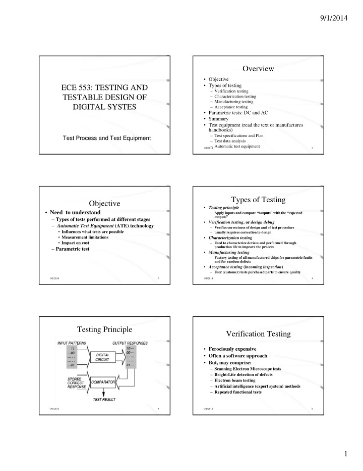
- Testing principle
– Apply inputs and compare “outputs” with the “expected
- utputs”
- Verification testing, or design debug
– Verifies correctness of design and of test procedure – usually requires correction to design
9/1/2014 4
- Characterization testing
– Used to characterize devices and performed through production life to improve the process
- Manufacturing testing
– Factory testing of all manufactured chips for parametric faults and for random defects
- Acceptance testing (incoming inspection)
– User (customer) tests purchased parts to ensure quality
Testing Principle
9/1/2014 5
Verification Testing
- Ferociously expensive
- Often a software approach
- But, may comprise:
9/1/2014 6