Overview Motivation and introduction Functional model of a memory - - PDF document

overview
SMART_READER_LITE
LIVE PREVIEW

Overview Motivation and introduction Functional model of a memory - - PDF document

10/28/2014 Overview Motivation and introduction Functional model of a memory ECE 553: TESTING AND A simple minded test and its limitations TESTABLE DESIGN OF Fault models DIGITAL SYSTES DIGITAL SYSTES March tests and


slide-1
SLIDE 1

10/28/2014 1

ECE 553: TESTING AND TESTABLE DESIGN OF DIGITAL SYSTES DIGITAL SYSTES

Memory testing

Overview

  • Motivation and introduction
  • Functional model of a memory
  • A simple minded test and its limitations
  • Fault models

10/28/2014 2

  • March tests and their capabilities
  • Neighborhood tests
  • Summary

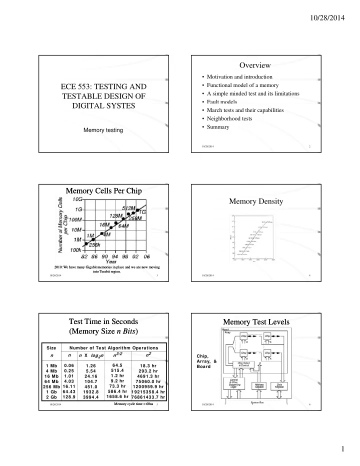
Memory Cells Per Chip Memory Cells Per Chip

10/28/2014 3

2010: We have many Gigabit memories in place and we are now moving into Terabit region. 2010: We have many Gigabit memories in place and we are now moving into Terabit region.

Memory Density

10/28/2014 4

Test Time in Seconds (Memory Size n Bits) Test Time in Seconds (Memory Size n Bits)

n n n X log2n n3/2 n2 Size Number of Test Algorithm Operations

10/28/2014 5

1 Mb 4 Mb 16 Mb 64 Mb 256 Mb 1 Gb 2 Gb 0.06 0.25 1.01 4.03 16.11 64.43 128.9 1.26 5.54 24.16 104.7 451.0 1932.8 3994.4 64.5 515.4 1.2 hr 9.2 hr 73.3 hr 586.4 hr 1658.6 hr 18.3 hr 293.2 hr 4691.3 hr 75060.0 hr 1200959.9 hr 19215358.4 hr 76861433.7 hr

Memory cycle time = 60ns Memory cycle time = 60ns

Memory Test Levels Memory Test Levels

Chip, Array &

10/28/2014 6

Array, & Board

slide-2
SLIDE 2

10/28/2014 2

Functional Model Functional Model

10/28/2014 7

Simplified Functional Model Simplified Functional Model

10/28/2014 8

A simple minded test

for cell := 0 to n - 1 (or any other order) do write 0 to A [cell]; read A [cell]; { Expected value = 0} write 1 to A [cell]; read A [cell]; { Expected value = 1 }

10/28/2014 9

read A [cell]; { Expected value 1 } end for; What does this test achieve? What kind of faults does it detect and it fault coverage?

Functional Faults Functional Faults

Fault SAF SAF SAF SAF SAF SAF CF a b c d e f g Functional fault Cell stuck Driver stuck Read/w rite line stuck Chip-select line stuck Data line stuck Open circuit in data line Short circuit betw een data lines

10/28/2014 10

CF AF AF AF AF AF AF TF NPSF g h i j k l m n

  • p

Crosstalk betw een data lines Address line stuck Open circuit in address line Shorts betw een address lines Open circuit in decoder Wrong address access Multiple simultaneous address access Cell can be set to 0 (1) but not to 1 (0) Pattern sensitive cell interaction

Reduced Functional Faults Reduced Functional Faults

Fault

10/28/2014 11

SAF TF CF NPSF Stuck-at fault Transition fault Coupling fault Neighborhood Pattern Sensitive fault

Stuck-at Faults Stuck-at Faults

  • Condition: For each cell, must read a 0 and a 1.

10/28/2014 12

slide-3
SLIDE 3

10/28/2014 3

Transition Faults Transition Faults

  • Cell fails to make 0 1 or 1 0 transition
  • Condition: Each cell must undergo a transition

and a transition, and be read after such, before d i f th t iti

10/28/2014 13

undergoing any further transitions.

< /0> transition fault

Coupling Faults Coupling Faults

  • Coupling Fault (CF): Transition in bit j causes

unwanted change in bit i

  • 2-Coupling Fault: Involves 2 cells, special case of k-

Coupling Fault

10/28/2014 14

– Must restrict k cells to make practical

  • Inversion and Idempotent CFs -- special cases of 2-

Coupling Faults

  • Bridging and State Coupling Faults involve any # of

cells, caused by logic level

  • Dynamic Coupling Fault (CFdyn) -- Read or write on j

forces i to 0 or 1

March Test Notation March Test Notation

  • r0 -- Read a 0 from a memory location
  • r1 -- Read a 1 from a memory location
  • w0 -- Write a 0 to a memory location

10/28/2014 15

y

  • w1 -- Write a 1 to a memory location
  • - Write a 1 to a cell containing 0
  • - Write a 0 to a cell containing 1

March Test Notation (Continued) March Test Notation (Continued)

  • - Complement the cell contents

10/28/2014 16

  • - Increasing memory addressing
  • - Decreasing memory addressing
  • - Either increasing or decreasing

MATS+ March Test MATS+ March Test

M0: { March element (w0) }

for cell := 0 to n - 1 (or any other order) do write 0 to A [cell];

M1: { March element (r0, w1) }

10/28/2014 17

for cell := 0 to n - 1 do read A [cell]; { Expected value = 0} write 1 to A [cell];

M2: {March element (r1, w0) }

for cell := n – 1 down to 0 do read A [cell]; { Expected value = 1 } write 0 to A [cell];

Address Decoder Faults (ADFs) Address Decoder Faults (ADFs)

  • Address decoding error assumptions:

– Decoder does not become sequential – Same behavior during both read & write

10/28/2014 18

  • Multiple ADFs must be tested for
  • Decoders have CMOS stuck-open faults
slide-4
SLIDE 4

10/28/2014 4

Theorem 9.2 Theorem 9.2

  • A March test satisfying conditions 1 & 2 detects all

address decoder faults.

  • ... Means any # of read or write operations
  • Before condition 1 must have wx element

10/28/2014 19

  • Before condition 1, must have wx element

– x can be 0 or 1, but must be consistent in test Condition 1 2 March element (rx, …, w x ) (r x , …, w x)

Proof Illustration Proof Illustration

Combinations that must be tested Combinations that must be tested Conditions for proof Conditions for proof

10/28/2014 20

Necessity Proof Necessity Proof

  • Removing rx from Condition 1 prevents A or B

fault detection when x read

  • Removing rx from Condition 2 prevents A or B

fault detection when x read

10/28/2014 21

fault detection when x read

  • Removing rx or wx from Condition 1 misses fault

D2

  • Removing rx or wx from condition 2 misses fault

D3

  • Removing both writes misses faults C and D1

Sufficiency Proof Sufficiency Proof

  • Faults A and B: Detected by SAF test
  • Fault C: Initialize memory to h (x or x). Subsequent

March element that reads h and writes h detects Fault C

10/28/2014 22

Fault C.

– Marching writes h to Av. Detection: read Aw – Marching writes h to Az. Detection: read Ay

  • Fault D: Memory returns random result when

multiple cells read simultaneously. Generate fault by writing Ax, Detection: read Aw or Ay ( or marches)

Irredundant March Tests Irredundant March Tests

Algorithm MATS MATS+ MATS++ MARCH X MARCH Description { (w 0); (r0, w 1); (r1) } { (w 0); (r0, w 1); (r1, w 0) } { (w 0); (r0, w 1); (r1, w 0, r0) } { (w 0); (r0, w 1); (r1, w 0); (r0) } { (w 0); (r0, w 1); (r1, w 0);

10/28/2014 23

C— MARCH A MARCH Y MARCH B { ( ); ( , ); ( , ); (r0, w 1); (r1, w 0); (r0) } { (w 0); (r0, w 1, w 0, w 1); (r1, w 0, w 1); (r1, w 0, w 1, w 0); (r0, w 1, w 0) } { (w 0); (r0, w 1, r1); (r1, w 0, r0); (r0) } { (w 0); (r0, w 1, r1, w 0, r0, w 1); (r1, w 0, w 1); (r1, w 0, w 1, w 0); (r0, w 1, w 0) }

Irredundant March Test Summary Irredundant March Test Summary

Algorithm MATS MATS+ SAF All All AF Some All TF CF in CF id CF dyn SCF Linked Faults

10/28/2014 24

MATS+ MATS++ MARCH X MARCH C— MARCH A MARCH Y MARCH B All All All All All All All All All All All All All All All All All All All All All All All All All All All All Some Some Some

slide-5
SLIDE 5

10/28/2014 5

March Test Complexity

Algorithm MATS MATS+ MATS++ Complexity 4n 5n 6

10/28/2014 25

MATS++ MARCH X MARCH C— MARCH A MARCH Y MARCH B 6n 6n 10n 15n 8n 17n

Neighborhood Pattern Sensitive Coupling Faults Neighborhood Pattern Sensitive Coupling Faults

10/28/2014 26

RAM Organization RAM Organization

10/28/2014 27

Notation Notation

  • ANPSF -- Active Neighborhood Pattern Sensitive

Fault

  • APNPSF – Active and Passive Neighborhood PSF
  • Neighborhood -- Immediate cluster of cells whose

10/28/2014 28

pattern makes base cell fail

  • NPSF -- Neighborhood Pattern Sensitive Fault
  • PNPSF -- Passive Neighborhood PSF
  • SNPSF -- Static Neighborhood Pattern Sensitive

Fault

Type 1 Active NPSF Type 1 Active NPSF

  • Active: Base cell changes when one deleted

neighborhood cell transitions

  • Condition for detection & location: Each base

cell must be read in state 0 and state 1, for all

10/28/2014 29

possible deleted neighborhood pattern changes.

Type 2 Active NPSF Type 2 Active NPSF

  • Used when diagonal couplings are significant,

and do not necessarily cause horizontal/vertical coupling

10/28/2014 30

slide-6
SLIDE 6

10/28/2014 6

Passive NPSF Passive NPSF

  • Passive: A certain neighborhood pattern

prevents the base cell from changing C di i f d i d l i

10/28/2014 31

  • Condition for detection and location: Each base

cell must be written and read in state 0 and in state 1, for all deleted neighborhood pattern changes.

Static NPSF Static NPSF

  • Static: Base cell forced into a particular state when

deleted neighborhood contains particular pattern.

  • Differs from active -- need not have a transition to

sensitive SNPSF

10/28/2014 32

sensitive SNPSF

  • Condition for detection and location: Apply all 0 and 1

combinations to k-cell neighborhood, and verify that each base cell was written.

Type 1 Tiling Neighborhoods Type 1 Tiling Neighborhoods

  • Write changes k different neighborhoods
  • Tiling Method: Cover all memory with non-
  • verlapping neighborhoods

10/28/2014 33

Two Group Method Two Group Method

  • Only for Type-1 neighborhoods
  • Use checkerboard pattern, cell is simultaneously a

base cell in group 1, and a deleted neighborhood cell in 2

10/28/2014 34

RAM Tests for Layout-Related Faults RAM Tests for Layout-Related Faults

Inductive Fault Analysis:

1 Generate defect sizes, location, layers

based on fabrication line model

10/28/2014 35

2 Place defects on layout model 3 Extract defective cell schematic &

electrical parameters

4 Evaluate cell testing

Memory Testing Summary Memory Testing Summary

  • Multiple fault models are essential
  • Combination of tests is essential:

– March – SRAM and DRAM

10/28/2014 36

– NPSF -- DRAM – DC Parametric -- Both – AC Parametric -- Both

  • Inductive Fault Analysis is now required
slide-7
SLIDE 7

10/28/2014 7

Summary

  • Functional and fault model of memory

– Many fault models

  • March tests and their capabilities

V i f

10/28/2014 37

– Variety of tests

  • Neighborhood pattern sensitive tests

– Varity of fault models and tests

  • Testing multiport memories – still being

investigated

10/28/2014 38

Appendix Density and Defect Trends Density and Defect Trends

  • 1970 -- DRAM Invention (Intel) 1024 bits
  • 1993 -- 1st 256 MBit DRAM papers
  • 1997 -- 1st 256 MBit DRAM samples

6

¢ ¢

10/28/2014 39

– 1 /bit --> 120 X 10-6 /bit

  • Kilburn -- Ferranti Atlas computer (Manchester U.) --

Invented Virtual Memory

– 1997 -- Cache DRAM -- SRAM cache + DRAM now on 1 chip ¢ ¢

Faults Faults

  • System -- Mixed electronic, electromechanical,

chemical, and photonic system (MEMS technology)

10/28/2014 40

  • Failure -- Incorrect or interrupted system

behavior

  • Error -- Manifestation of fault in system
  • Fault -- Physical difference between good &

bad system behavior

Fault Types Fault Types

  • Fault types:

– Permanent -- System is broken and stays broken the same way indefinitely T i t F lt t il ff t th

10/28/2014 41

– Transient -- Fault temporarily affects the system behavior, and then the system reverts to the good machine -- time dependency, caused by environmental condition – Intermittent -- Sometimes causes a failure, sometimes does not

Failure Mechanisms Failure Mechanisms

  • Permanent faults:

– Missing/Added Electrical Connection – Broken Component (IC mask defect or silicon-to- metal connection)

10/28/2014 42

metal connection) – Burnt-out Chip Wire – Corroded connection between chip & package – Chip logic error (Pentium division bug)

slide-8
SLIDE 8

10/28/2014 8

Failure Mechanisms (Continued) Failure Mechanisms (Continued)

  • Transient Faults:

– Cosmic Ray – An α particle (ionized Helium atom) – Air pollution (causes wire short/open) – Humidity (temporary short)

10/28/2014 43

– Humidity (temporary short) – Temperature (temporary logic error) – Pressure (temporary wire open/short) – Vibration (temporary wire open) – Power Supply Fluctuation (logic error) – Electromagnetic Interference (coupling) – Static Electrical Discharge (change state) – Ground Loop (misinterpreted logic value)

Failure Mechanisms (Continued) Failure Mechanisms (Continued)

  • Intermittent Faults:

– Loose Connections – Aging Components (changed logic delays) – Hazards and Races in critical timing paths (bad design)

10/28/2014 44

Hazards and Races in critical timing paths (bad design) – Resistor, Capacitor, Inductor variances (timing faults) – Physical Irregularities (narrow wire -- high resistance) – Electrical Noise (memory state changes)

Physical Failure Mechanisms Physical Failure Mechanisms

  • Corrosion
  • Electromigration
  • Bonding Deterioration -- Au package wires

interdiffuse with Al chip pads

10/28/2014 45

  • Ionic Contamination -- Na+ diffuses through package

and into FET gate oxide

  • Alloying -- Al migrates from metal layers into Si

substrate

  • Radiation and Cosmic Rays -- 8 MeV, collides with Si

lattice, generates n - p pairs, causes soft memory error

Fault Modeling Fault Modeling

  • Behavioral (black-box) Model -- State machine

modeling all memory content combinations -- Intractable

10/28/2014 46

  • Functional (gray-box) Model -- Used
  • Logic Gate Model -- Not used Inadequately

models transistors & capacitors

  • Electrical Model -- Very expensive
  • Geometrical Model -- Layout Model

– Used with Inductive Fault Analysis

Reduced Functional Model (van de Goor) Reduced Functional Model (van de Goor)

  • n Memory bits, B bits/word, n/B addresses
  • Access happens when Address Latch contents change
  • Low-order address bits operate column decoder,

10/28/2014 47

high-order operate row decoder

  • read -- Precharge bit lines, then activate row
  • write -- Keep driving bit lines during evaluation
  • Refresh -- Read all bits in 1 row and simultaneously

refresh them

Inversion Coupling Faults (CFin) Inversion Coupling Faults (CFin)

  • r in cell j inverts contents of cell i
  • Condition: For all cells that are coupled, each

should be read after a series of possible CFins

10/28/2014 48

should be read after a series of possible CFins may have occurred, and the # of coupled cell transitions must be odd (to prevent the CFins from masking each other).

  • < ; > and < ; >
slide-9
SLIDE 9

10/28/2014 9

Good Machine State Transition Diagram Good Machine State Transition Diagram

10/28/2014 49

CFin State Transition Diagram CFin State Transition Diagram

10/28/2014 50

Idempotent Coupling Faults (CFid) Idempotent Coupling Faults (CFid)

  • r transition in j sets cell i to 0 or 1
  • Condition: For all coupled faults, each should be read

after a series of possible CFids may have happened,

10/28/2014 51

p y pp , such that the sensitized CFids do not mask each

  • ther.
  • Asymmetric: coupled cell only does or
  • Symmetric: coupled cell does both due to fault
  • < ; 0>, < ; 1>, < ; 0>, < ; 1>

CFid Example CFid Example

10/28/2014 52

Dynamic Coupling Faults (CFdyn) Dynamic Coupling Faults (CFdyn)

  • Read or write in cell of 1 word forces cell in

different word to 0 or 1

10/28/2014 53

  • <r0 | w0 ; 0>, <r0 | w0 ; 1>, < r1

| w1 ; 0>, and <r1 | w1; 1>

– | Denotes “OR” of two operations

  • More general than CFid, because a CFdyn can

be sensitized by any read or write operation

Bridging Faults Bridging Faults

  • Short circuit between 2+ cells or lines
  • 0 or 1 state of coupling cell, rather than coupling cell

transition, causes coupled cell change

10/28/2014 54

, p g

  • Bidirectional fault -- i affects j, j affects i
  • AND Bridging Faults (ABF):

– < 0,0 / 0,0 >, <0,1 / 0,0 >, <1,0 / 0,0>, <1,1 / 1,1>

  • OR Bridging Faults (OBF):

– < 0,0 / 0,0 >, <0,1 / 1,1 >, <1,0 / 1,1>, <1,1 / 1,1>

slide-10
SLIDE 10

10/28/2014 10

State Coupling Faults State Coupling Faults

  • Coupling cell / line j is in a given state y that forces

coupled cell / line i into state x

  • < 0;0 >, < 0;1 >, < 1;0 >, < 1;1 >

10/28/2014 55

Fault Modeling Example 1 Fault Modeling Example 1

SA0

AF+SAF

SAF

10/28/2014 56

SCF<0;0> SCF<1;1>

SA0

SA0

TF< /1> TF< /0>

Fault Modeling Example 2 Fault Modeling Example 2

SA1 SA1+SCF

gg

10/28/2014 57

ABF ABF

SA0

ABF

SCF

Multiple Fault Models Multiple Fault Models

  • Coupling Faults: In real manufacturing, any # can
  • ccur simultaneously
  • Linkage: A fault influences behavior of another
  • Example March test that fails:

10/28/2014 58

– { (w0) ; (r0, w1); (w0, w1); (r1)} – Works only when faults not linked

Fault Hierarchy Fault Hierarchy

10/28/2014 59

Tests for Linked AFs Tests for Linked AFs

  • Cases 1, 2, 3 & 5 -- Unlinked
  • Cases 4 & 6 -- Linked

10/28/2014 60

slide-11
SLIDE 11

10/28/2014 11

DRAM/SRAM Fault Modeling DRAM/SRAM Fault Modeling

DRAM or SRAM Faults Shorts & opens in memory cell array Shorts & opens in address decoder Access time failures in address decoder Coupling capacitances betw een cells Bit line shorted to word line Model SAF,SCF AF Functional CF IDDQ

10/28/2014 61

Bit line shorted to word line Transistor gate shorted to channel Transistor stuck-open fault Pattern sensitive fault Diode-connected transistor 2 cell short Open transistor drain Gate oxide short Bridging fault IDDQ IDDQ SOF PSF

SRAM Only Fault Modeling SRAM Only Fault Modeling

Faults found only in SRAM Model

10/28/2014 62

Open-circuited pull-up device Excessive bit line coupling capacitance DRF CF

DRAM Only Fault Modeling

Faults only in DRAM Data retention fault (sleeping sickness) Refresh line stuck-at fault Model DRF SAF

10/28/2014 63

Bit-line voltage imbalance fault Coupling betw een word and bit line Single-ended bit-line voltage shift Precharge and decoder clock overlap PSF CF PSF AF

Functional RAM Testing with March Tests Functional RAM Testing with March Tests

  • March Tests can detect AFs -- NPSF

Tests Cannot

10/28/2014 64

  • Conditions for AF detection:

– Need ( r x, w x) – Need ( r x, w x)

MATS+ Example Cell (2,1) SA0 Fault MATS+ Example Cell (2,1) SA0 Fault

10/28/2014 65

MATS+: { M0: (w 0); M1: (r0, w 1); M2: (r1, w 0) }

MATS+ Example Cell (2, 1) SA1 Fault MATS+ Example Cell (2, 1) SA1 Fault

10/28/2014 66

MATS+: { M0: (w 0); M1: (r0, w 1); M2: (r1, w 0) }

slide-12
SLIDE 12

10/28/2014 12

MATS+ Example Multiple AF Type C MATS+ Example Multiple AF Type C

  • Cell (2,1) is not addressable
  • Address (2,1) maps into (3,1) & vice versa
  • Can’t write (2,1), read (2,1) gives random #

10/28/2014 67

MATS+: { M0: (w 0); M1: (r0, w 1); M2: (r1), w 0 }