overview
play

Overview Motivation ECE 553: TESTING AND What is simulation? - PDF document

9/18/2014 Overview Motivation ECE 553: TESTING AND What is simulation? Design verification TESTABLE DESIGN OF Circuit modeling Circuit modeling DIGITAL SYSTES DIGITAL SYSTES Determining signal values True-value


  1. 9/18/2014 Overview • Motivation ECE 553: TESTING AND • What is simulation? • Design verification TESTABLE DESIGN OF • Circuit modeling Circuit modeling DIGITAL SYSTES DIGITAL SYSTES • Determining signal values • True-value simulation algorithms • Compiled-code simulation • Event-driven simulation Logic Simulation • Summary 9/18/2014 2 Simulation Defined Motivation • Definition: Simulation refers to modeling of a design, its function and performance. • Logic simulation is used to verify or • A software simulator is a computer program; an ascertain assertions (design, device, …) emulator is a hardware simulator. • It avoids building costly hardware • Simulation is used for design verification: • Can help debug a design in many more • Validate assumptions • Verify logic ways than the real hardware could • Verify performance (timing) • Types of simulation: • Understanding simulation will help • Logic or switch level understand the limitations of the simulation • Timing process and the simulator(s) in question • Circuit • Fault 9/18/2014 3 9/18/2014 4 
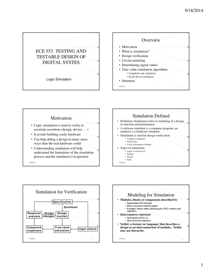
Simulation for Verification Modeling for Simulation • Modules, blocks or components described by Specification • Input/output (I/O) function • Delays associated with I/O signals Synthesis • Examples: binary adder, Boolean gates, FET, resistors and capacitors Response Response Design Design Design Design • Interconnects represent I analysis changes (netlist) • ideal signal carriers, or • ideal electrical conductors • Netlist: a format (or language) that describes a design as an interconnection of modules. Netlist Computed True-value Input stimuli may use hierarchy. responses simulation 9/18/2014 5 9/18/2014 6 1

  2. 9/18/2014 Options for Inertial Delay Logic Model of MOS Circuit (simulation of a NAND gate) Transient V DD pMOS FETs a Inputs region a D a c D c b a b D b C a c c (CMOS) C c C c b b D a and D b are Logic simulation c (zero delay) C b interconnect or nMOS FETs propagation delays c (unit delay) rise=5, fall=3 c (multiple delay) D c is inertial delay C a , C b and C c are of gate Unknow n (X) c (minmax delay) min =2, max =5 parasitic capacitances 0 5 Time units 9/18/2014 7 9/18/2014 8 Determining Gate Values Signal States • Two-states (0, 1) can be used for purely • Use of software logic primitives such as combinational logic with zero-delay. AND, OR, NOT instructions • Three-states (0, 1, X) are essential for timing • Search the truth table hazards and for sequential logic initialization. • Four-states (0, 1, X, Z) are essential for MOS • Use cubes and cube intersection rules for devices See example below devices. See example below. processing i • Analog signals are used for exact timing of digital • Use of X value and its processing logic and for analog circuits. – Example: x value simulation, problems associated with it, possible fixes and conservative Z (hold previous value) processing 0 0 9/18/2014 9 9/18/2014 10 True-Value Simulation Algorithms Compiled-Code Algorithm • Compiled-code simulation • Step 1: Levelize combinational logic and encode in a • Applicable to zero-delay combinational logic compilable programming language • Also used for cycle-accurate synchronous sequential circuits for logic verification • Step 2: Initialize internal state variables (flip-flops) • Efficient for highly active circuits, but inefficient for low-activity circuits • Step 3: For each input vector St 3 F h i t t • High-level (e.g., C language) models can be used Hi h l l ( C l ) d l b d • Event-driven simulation – Set primary input variables • Only gates or modules with input events are evaluated ( event means a – Repeat (until steady-state or max. iterations) signal change ) • Execute compiled code • Delays can be accurately simulated for timing verification – Report or save computed variables • Efficient for low-activity circuits • Can be extended for fault simulation 9/18/2014 11 9/18/2014 12 2

  3. 9/18/2014 Time Wheel (Circular Stack) Event-Driven Algorithm (Example) Scheduled Activity events list max a =1 e =1 Current t = 0 c = 0 d, e 2 time t=0 c =1 0 pointer Event link-list 1 g =1 1 2 2 2 d = 1, e = 0 f, g 2 d = 0 d = 0 Time stack 3 3 4 f =0 b =1 4 g = 0 4 5 5 g 6 6 f = 1 g 7 0 4 8 Time, t 7 8 g = 1 9/18/2014 13 9/18/2014 14 Efficiency of Event-driven Summary Simulator • Logic or true-value simulators are essential tools for • Simulates events (value changes) only design verification. • Speed up over compiled-code can be ten times • Verification vectors and expected responses are or more; in large logic circuits about 0.1 to generated (often manually) from specifications. 10% gates become active for an input change 10% gates become active for an input change • A logic simulator can be implemented using either A l i i l b i l d i i h compiled-code or event-driven method. • Per vector complexity of a logic simulator is Steady 0 Large logic Steady 0 approximately linear in circuit size. block w ithout (no event) activity 0 to 1 event • Modeling level determines the evaluation procedures used in the simulator. 9/18/2014 15 9/18/2014 16 3

Download Presentation
Download Policy: The content available on the website is offered to you 'AS IS' for your personal information and use only. It cannot be commercialized, licensed, or distributed on other websites without prior consent from the author. To download a presentation, simply click this link. If you encounter any difficulties during the download process, it's possible that the publisher has removed the file from their server.

Recommend


More recommend