SLIDE 1 Moment
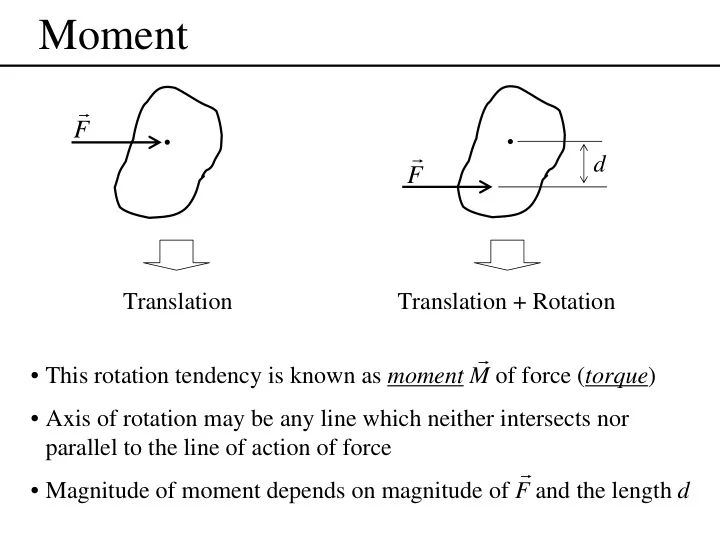
F r F r
d Translation Translation + Rotation
- This rotation tendency is known as moment M of force (torque)
- Axis of rotation may be any line which neither intersects nor
parallel to the line of action of force
- Magnitude of moment depends on magnitude of F and the length d
r r
SLIDE 2 A O O
r d α
F r M r F r
d
A
Μ=Fd +
Mathematical definition
Moment about axis O-O is defined as
M = Fd
Moment is a vector Direction, normal to r-F plane (right hand rule) Axis O-O is called moment axis (N.m) Moment is a sliding vector
- Axis becomes point
- Use sign convention to express
direction (+ for CCW, − for CW) 2-D
SLIDE 3 The cross product
A O O
r d α
F r M r
The moment of about point A =
F r F r M r r r × =
Magnitude M = Frsin(α) = Fd
- Direction: normal to the r – F plane, right hand rule
- xyz axis have to satisfy the right hand rule;
- Sequence of r and F is important;
k j i ˆ ˆ ˆ = ×
r F F r r r r r × ≠ ×
SLIDE 4 Varignon’s theorem
=
The moment of the components
- f the force about the same point
The moment of a force about any point
O
r
F r
A
1
F r
2
F r
2 1
F F F r r r + =
) (
2 1
F F r F r M o r r r r r r + × = × =
2 1
F r F r M o r r r r r × + × =
+
O
F r
x y d1 d2
x
F r
y
F r
Mo = Fxd2-Fyd1
Useful with rectangular components Can use with more than 2 components
SLIDE 5
Sample (1)
Calculate the magnitude of the moment about the base point O of the 600-N force.
SLIDE 6 Sample (2)
The force exerted by the plunger of cylinder AB on the door is 40 N directed along the line AB, and this force tends to keep the door closed. Compute the moment of this force about the hinge
- O. What force Fc normal to the plane of the door must the door
stop at C exert on the door so that the combined moment about O of the two forces is zero?
SLIDE 7 Couple (1)
O
F r F r −
a d
+ Couple is a moment produced by two equal,
- pposite, and noncollinear forces.
The moment of a couple has the same value for all moment centers M = F(a+d) – Fa = Fd F r r F r F r M
B A B A
r r r r r r r r × − = − × + × = ) ( ) (
O
F r F r −
A
r r
B
r r r r
A B
M r
F r M r r r × =
- Couple may be represented as a free vector
- Direction of couple is normal to the plane of
two force
SLIDE 8 Couple (2)
M M M M CCW couple CW couple Since couple is a free vector, the followings are equivalent couples
F F
M r
F F
M r
≡
F F
M r
≡ ≡
2F 2F
M r
d/2 d
SLIDE 9 Force-couple systems
A given force can be replaced by an equal parallel force and a couple.
≡ ≡
A
F r
B A B
M=Fd
A
F r
d
F r − F r
B A
F r F r F r −
d
B Couple
Force-couple system
No changes in the net external effect
Add to the system
SLIDE 10 Sample (3)
The rigid structural member is subjected to a couple consisting of the two 100-N forces. Replace this couple by an equivalent couple consisting of the two forces P and –P, each
- f which has a magnitude of 400 N.
Determine the proper angle θ.
SLIDE 11
Sample (4)
Replace the horizontal 400-N force acting on the lever by an equivalent system consisting of a force at O and a couple.
SLIDE 12
Sample (5)
Calculate the moment of the 1200-N force about pin A of the bracket. Begin by replacing the 1200-N force by a force-couple system at point C.
SLIDE 13 Sample (6)
Determine the combined moment MA about point A due to the two equal tensions T = 8 kN in the cable acting on the pulley. Is it necessary to know the pulley diameter?
0.8 m 1.6 m 0.8 m 1.6 m T T A B C 45°
SLIDE 14 Resultants
The Resultant is the simplest force combination which can replace the original forces without altering the external effect on the body
2
F r
1
F r
3
F r
1
R r R r
1
R r
1 3 2
R F F r r r = + R F R r r r = +
1 1
(1) (2)
1
F r
2
F r
3
F r
R r
y x
y
F
1 y
F2
y
F3
y
R
x
F
1 x
F2
x
F3
x
R
θ
∑
= + + + = F F F F R r r r r r ...
3 2 1
,
∑
=
x x
F R
∑
=
y y
F R
2 2
) ( ) (
∑ ∑
+ =
y x
F F R ) / ( tan 1
x y R
R
−
= θ
SLIDE 15 O
Method to get a resultant
1) Pick a point (easy to find moment arms)
2
F r
1
F
3
F r r
O d
1
d
2
d
3
2) Replace each force with a force at point O + a couple
2
F r
1
F r
3
F r
O F1d1 F2d2 F3d3
3) Add forces and moments 4) Replace force-couple system with a single force
R r O d=Mo/R Mo=Rd Mo=Σ(Fidi )
∑
= F R r r
SLIDE 16 Other cases
2
F r
1
F r
3
F r
3 2 1
F F F r r r − = + d
∑
= 0 F r d F M R
O
⋅ = =
3
2
F r
1
F r
3
F r
O
∑
= 0
O
M r
∑
= F R r r
SLIDE 17
Sample (7)
Determine the resultant of the four forces and one couple that act on the plate shown.
SLIDE 18 Sample (8)
Determine and locate the resultant R
- f the two force and one couple acting
- n the I-beam.
SLIDE 19
Sample (9)
The five vertical loads represent the effect of the weights of the truss and supported roofing materials. The 400-N load represents the effect of wind pressure. Determine the equivalent force-couple system at A. Also, compute the x-intercept of the line of action of the system resultant treated as a single force R.
SLIDE 20
Sample (10)
Replace the three forces acting on the bent pipe by a single equivalent force R. Specify the distance x from point O to the point on the x-axis through which the line of action of R passes.