Material properties evaluation of multi-layered ATF cladding using - - PDF document

material properties evaluation of multi layered atf
SMART_READER_LITE
LIVE PREVIEW

Material properties evaluation of multi-layered ATF cladding using - - PDF document

Transactions of the Korean Nuclear Society Virtual Spring Meeting July 9-10, 2020 Material properties evaluation of multi-layered ATF cladding using instrumented micro- indentation techniques Jong-Dae Hong a , Dong-Hyun Kim a , Sung Geun Kim


slide-1
SLIDE 1

Material properties evaluation of multi-layered ATF cladding using instrumented micro- indentation techniques

Jong-Dae Hong a, Dong-Hyun Kim a, Sung Geun Kim b, Hongryul Oh a, Jae-Yong Kim a, Hyun-Gil Kima

a ATF Technology Development Division, Korea Atomic Energy Research Institute b Post Irradiation Examination Facility Team, Korea Atomic Energy Research Institute

989-111 Daedeok-daero, Yuseong-gu, Daejeon, 34057, Rep. of Korea

*Corresponding author: jongd@kaeri.re.kr

  • 1. Introduction

To meet increased need for safety under accident conditions after Fukushima accident, the development

  • f accident tolerant fuel (ATF) cladding is motivated.

From a near-term point of view, the coating techniques

  • f oxidation resistant material, such as Cr and Al, on the

existing Zr-alloy cladding have been applied. Meanwhile, the reliable fuel performance assessment in both normal and abnormal conditions needs well-proven fuel performance code and material properties. But, there is no data to describe the coating layer on Zr-based matrix, only available for a bulk coating material or the whole coated cladding. The general thickness of coating layer is below tens of micrometer, therefore, it is impossible to perform tensile test directly due to its small size. In this regards, the instrumented indentation technique (IIT) in micro-level is introduced to evaluate the mechanical properties. IIT could evaluate the mechanical properties by recording variation in indentaion load and depth. In this paper, preliminary results are presented for one of the KAERI developed ATF claddings, partially oxide-dispersion- strengthened (ODS) - treated Zr-alloy cladding.

  • 2. Experimental

2.1 Test Material [1,2] The base material used in this study was commercial grade Zircaloy-4 cladding, which has been used in PWR fuel cladding. The initial cladding thickness (t) and

  • uter diameter (OD) were 0.57 mm and 9.5 mm. A

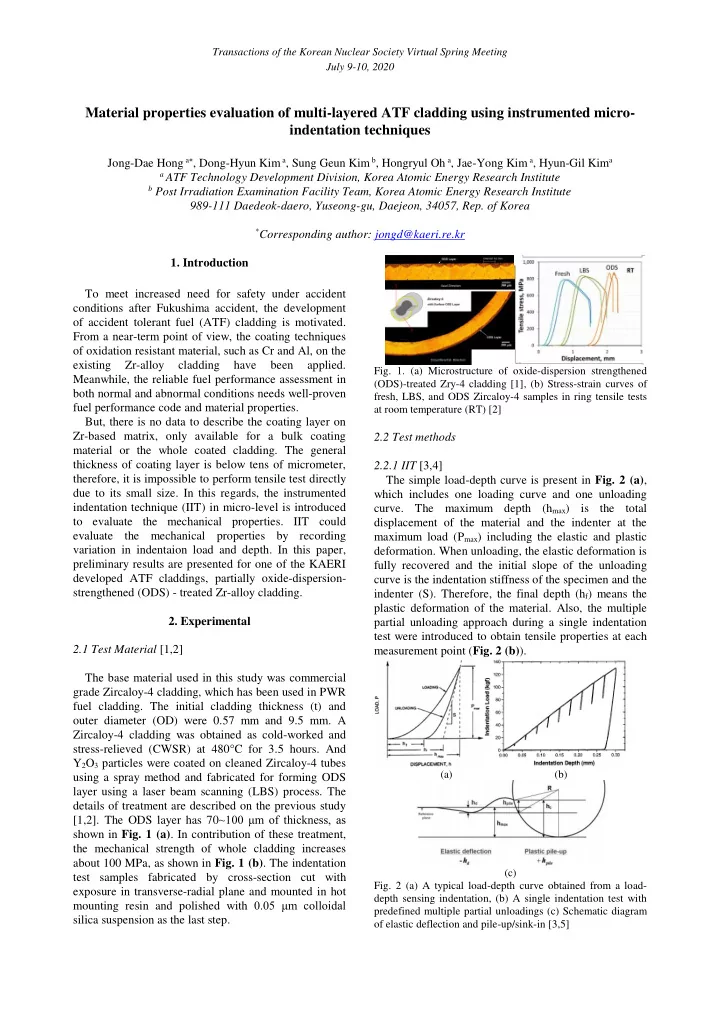
Zircaloy-4 cladding was obtained as cold-worked and stress-relieved (CWSR) at 480°C for 3.5 hours. And Y2O3 particles were coated on cleaned Zircaloy-4 tubes using a spray method and fabricated for forming ODS layer using a laser beam scanning (LBS) process. The details of treatment are described on the previous study [1,2]. The ODS layer has 70~100 μm of thickness, as shown in Fig. 1 (a). In contribution of these treatment, the mechanical strength of whole cladding increases about 100 MPa, as shown in Fig. 1 (b). The indentation test samples fabricated by cross-section cut with exposure in transverse-radial plane and mounted in hot mounting resin and polished with 0.05 μm colloidal silica suspension as the last step.

  • Fig. 1. (a) Microstructure of oxide-dispersion strengthened

(ODS)-treated Zry-4 cladding [1], (b) Stress-strain curves of fresh, LBS, and ODS Zircaloy-4 samples in ring tensile tests at room temperature (RT) [2]

2.2 Test methods 2.2.1 IIT [3,4] The simple load-depth curve is present in Fig. 2 (a), which includes one loading curve and one unloading

  • curve. The maximum depth (hmax) is the total

displacement of the material and the indenter at the maximum load (Pmax) including the elastic and plastic

  • deformation. When unloading, the elastic deformation is

fully recovered and the initial slope of the unloading curve is the indentation stiffness of the specimen and the indenter (S). Therefore, the final depth (hf) means the plastic deformation of the material. Also, the multiple partial unloading approach during a single indentation test were introduced to obtain tensile properties at each measurement point (Fig. 2 (b)).

(a) (b) (c)

  • Fig. 2 (a) A typical load-depth curve obtained from a load-

depth sensing indentation, (b) A single indentation test with predefined multiple partial unloadings (c) Schematic diagram

  • f elastic deflection and pile-up/sink-in [3,5]

Transactions of the Korean Nuclear Society Virtual Spring Meeting July 9-10, 2020

slide-2
SLIDE 2

The strain (ε) is derived by differentiating the displacement in the depth direction (Eq. (1)).

R a R a

2

) / ( 1 (    

(1) where α, R, a is the fitting constant (=0.12), the indenter radius and a contact radius, respectively. The true stress is proportional to mean contact pressure in the fully plastic stage. Therefore, true stress is defined as Eq. (2).

2

1 a P     (2) where P, ψ is the indentation load and plastic constraint factor (=3.5), respectively. Indentation depth is different to contact depth due to elastic deflection phenomenon and pile-up/sink-in (Fig. 2 (c)), therefore, a calibrated contact depth (hc*) can be quantitatively defined as Eq. (3) and (4). S P w h hc

max max *

  (3) ) 2 ( ) 4 ( ) 2 ( 2 5 ) 4 ( ) 2 ( 2 5

2 * * 2 * 2 c c

h Rh n n a n n a        (4) where a* is the contact radius calculated from hc* and n is the work-hardening exponent. w is indentor shape factor and 0.75 for spherical indentor. The true strain and the true stress calculated by Eq. (1) and Eq. (2) are inserted into following Hollomon equation.

n

K  

(5) where K is a strength coefficient. The iteration is performed until n in Eq. (4) and Eq. (5) are the same. More details are described in ISO/TR 23981 and previous study [3-5]. 2.2.2 Test condition The multiple partial unloadings indentation test at RT were performed at each layer by micro-indentation tester (Micro-AIS, Frontics Inc.) with a 50 μm radius spherical diamond indenter (Fig. 3). The number of the cycle of indentation loading-unloading is 8 and the indentation depth at each step increase by 1 μm. The loading–unloading rates were at 0.02 mm/min with 500 ms of dwell time and 50 % unloading at each step. Also, the distance between each indents was 150 μm to prevent the influence of neighboring indent. At each layer, multiple tests were performed to confirm the data scatter and reproducibility.

  • Fig. 3. Photo of instrumented micro-indentation tester
  • 3. Results and Discussion

3.1 Zircaloy-4 base material

  • Fig. 4 (a) shows the representative load–depth

(displacement) curves of Zircaloy-4 obtained in this

  • study. According to procedures described in Section

2.2.1. 8 representative stress and strain values can be determined by analyzing each unloading curve according to the above procedure, then the values can be fitted as a simple power-law-type Hollomon Eq. (5). By iteration procedures, values of the work-hardening exponent and strength coefficient are calculated by the iteration method. The estimated yield strength (YS) and ultimate tensile strength (UTS) is 449.27±29.01 MPa and 615.49±38.90 MPa, respectively. Meanwhile, the diameter of circular indent was about 40 μm.

(a) (b)

  • Fig. 4. (a) The load-depth curve of Zircaloy-4 base material

(b) Resulting true stress-strain curve of Zircaloy-4 base material

3.2 ODS treated cladding Using the identical approaches, the micro-indentation tests were performed at each layer of ODS treated

  • cladding. As the diameter of circular indent at ODS

layer was about 32 μm, it is possible to measure the characteristics of ODS layer only which thickness is 80~100μm. Fig. 5 shows the resulting true stress-strain curve of ODS treated cladding with comparison to Zircaloy-4 base material. The estimated yield strength (YS) of ODS layer and HAZ (heat affected zone) is 971.13±66.24 MPa and 610.32±57.49 MPa,

  • respectively. The strengthening effect for ODS layer

and HAZ were confirmed quantitatively. This tendency corresponds to the results of bulk testing as Fig. 1 (b).

  • Fig. 5. Resulting true stress-strain curve of ODS treated

cladding with comparison to Zircaloy-4 base material Transactions of the Korean Nuclear Society Virtual Spring Meeting July 9-10, 2020

slide-3
SLIDE 3
  • 3. Conclusions

To acquire the local property of multi-layered ATF cladding, the instrumented micro-indentation techniques are introduced. Using this technique, the mechanical properties were obtained for thin ODS layer as well as HAZ and Zircaloy-4 base material, successfully. Also, it is considered that IIT could be adopted for thiner coating by an optimizing of load depth. ACKNOWLEDGEMENT This work has been carried out under the Nuclear R&D Program supported by the Ministry of Science and

  • ICT. (NRF-2017M2A8A5015064)

REFERENCES

[1] Y.I. Jung, H.G. Kim, H.U. Guim, Y.S. Lim, J.H. Park, D.J. Park, J.H. Yang, App. Surf. Sci. 429 (2018) 272-277. [2] Y.I. Jung, D.J. Park, J.H. Park, H.G. Kim, J.H. Yang, Y.H. Koo, Nucl. Eng. Technol. 50 (2018) 218-222. [3] E. Jeon, J.-S. Park, D. Kwon, J. Eng. Mater. Technol. 125 (2003) 406-411 [4] “ISO/TR 29381, Metallic Materials - Measurement of Mechanical Properties by an Instrumented Indentation Test – Indentation Tensile Properties, 3-10, ISO, Switzerland, (2008). [5] S.H. Kim, B.W. Lee, Y. Choi, D. Kwon, Mater. Sci. Eng. A-Struct. 415 (2006) 59-65 Transactions of the Korean Nuclear Society Virtual Spring Meeting July 9-10, 2020