SLIDE 1 1 of 19 POWER HOUSE FD & ID FANS ANALYZING CONCRETE FOUNDATION RESONANCE Ken Singleton Manager KSC Consulting LLC, Bristol VA ksingleton@vibrationconsulting.com Bob McGinnis, P.E. McGinnis Engineering LLC, Kingsport TN Abstract: A request was received to investigate high amplitude vibration of forced draft (FD) and induced draft (ID) fans at a coal fired power plant. Operating deflection shape analysis (ODS) and experimental modal analysis (EMA) were specifically requested. Of most concern was reported vibration amplitude over 0.40 in/sec pk on the ID Fan A outboard bearing. Steel bracing had been bolted to the ID Fan’s outboard pedestals in an attempt to reduce vibration. In-place balancing had been performed but was not effective in reducing the primarily axial direction vibration. Vibration data on the motor and fan bearing housings were monitored by a System 1 online acquisition system acquiring data from velometers. Proximity probes were not installed in the fluid film bearings. During three days onsite, test data were measured that included standard vibration data, ODS, EMA and multi-channel continuous data acquisition. Natural frequencies of the outboard pedestal of ID Fan A, inadequate hold down bolt tightness, inadequate and improper bracing and weak foundations were some of the problems identified. Recommendations were provided to increase stiffness of the ID and FD fan’s outboard pedestals by redesigning braces to bolt to a large concrete mass and addressing bearing housing, pedestal and motor bolting issues. Keywords: Bearing housing, experimental modal analysis, hold down bolts, operating deflection shape analysis, pedestal, resonance. Background: The power plant went into commercial service June 2008. The two ID Fans were direct coupled to 3950 HP, 1196 RPM motors using grid couplings. Concrete foundations were poured, then it appeared that the fan pedestals and motor pedestals were poured later. The fan rotors were supported in Dodge Sleevoil babbitted bearings. The ID Fan rotors weighted 30,038 lbs. Rotors were reported balanced to ISO 1940-1 balance quality G 2.5 which calculated to 57 oz-in at the drive end and 55 oz-in opposite drive end. ID Fan motor bearings were babbitted while the FD Fan motors were equipped with rolling element bearings. Visual Inspection: Before any vibration data was taken, a thorough visual inspection was made of all fans. This inspection identified several items as follows:
- The ID Fan bearing housings were bolted to fabricated
steel bases which were bolted to soleplates. The soleplates were bolted and grouted to the concrete
- pedestals. The pedestals appeared undersized for the
30,000 lbf fan rotor.
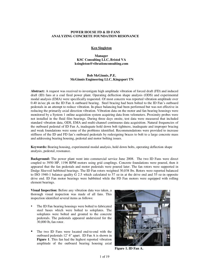
- The two ID Fans were located end-to-end with the
- utboard pedestals 12’ 6” apart. ID Fan A is shown in
Figure 1. This fan had the highest reported vibration amplitude of the outboard bearing housing axial Figure 1. ID Fan A.
SLIDE 2 2 of 19
- direction. Vibration had reportedly exceeded 0.40 in/sec pk. A Steel brace had been installed in an
attempt to reduce the bearing housing axial vibration. The brace was fabricated of 8” square tubing and bolted to both ID Fan’s outboard pedestals, as shown in Figures 2 & 3.
- Bracing had also been installed on the FD Fan’s outboard fan
pedestals, Figure 4. These braces were also fabricated of 8” square tubing and installed at 25 degree angle. Access to the bearings was by ladder. Brace plates were bolted to the concrete pedestal and concrete floor. The brace was not completely effective in reducing vibration to acceptable amplitudes.
- ID and FD fan’s concrete foundations had many cracks that
appeared to extend deep within the foundations, Figure 5. The quality of the concrete appeared substandard.
- ID and FD Fan concrete pedestals did not appear bonded to the
concrete foundations although rebar likely extended from the foundation up into the pedestals. Drawings were not available to verify construction details. The joint was cracked at the interface of the pedestals and foundation, shown by photo of ID Fan A outboard pedestal, Figure 6. Figure 5. ID Fan A Foundation Crack. Figure 3. ID Fan A & B, Outboard Pedestals, Steel Bracing Bolted to Each Pedestal. Figure 4: ID Fan A Outboard Bearing Pedestal Single Brace 30 Deg Angle. Figure 2. Brace of 8” Square Tubing Bolted to ID Fan Outboard Bearing Concrete Pedestals.
Attachment Plate 16” X 16”.
SLIDE 3 3 of 19
- FD Fan A Motor OB Bearing was not accessible
from the platform.
- No proximity probes were installed in the Dodge
Sleevoil bearings. Vibration monitoring was by GE Bently System 1 acquiring data from velometers magnetically attached to the bearing housings or stud mounted to brackets bolted to the housings.
- ID Fan bearing housing hold down bolts used
thin washers under the bolt heads. The slotted holes in the bearing housings for hold down bolts were very large, see Figure 7. Much thicker washers were needed to insure adequate clamping force without yielding of the washers.
- ID Fans A & B Motor hold down bolts to a
fabricated base used tapped holes in 1” thick steel instead of through bolting with washers and nuts, Figure 8. Initial Vibration Data on ID & FD Fans: The initial vibration survey of ID Fan A & B motor and fan bearing housings showed highest amplitude vibration at 2X the fan shaft’s rotational frequency. FD Fan A motor drive end bearing housing vibration data indicated a rolling element bearing defect. Per verbal information, a bearing had failed previously at this location. Overall vibration data on the motor and fan bearing housings of ID Fan A showed that the outboard bearing housing axial vibration at 0.36 in/sec pk was the point with highest amplitude, see Figure 9. Note that the chart shows AMCA Alarm Filter Out (overall) for Startup (Green), Alarm (Yellow) and Shutdown (Red). Data at 1X the shaft’s rotational frequency showed vibration amplitudes at all points were acceptable, as shown in Figure 10. The chart shows AMCA Filter in (1X) recommended Startup (Green) and Shutdown (Red). AMCA does not publish an alarm value for Alert (Yellow). Vibration at 2X measured on the motor and fan bearing housings is shown in Figure 11. The outboard bearing housing clearly had the highest vibration amplitude in the axial direction at 2X the rotor rotational frequency. AMCA does not publish vibration tolerances for the 2X frequency so the alarm levels are estimated. Figure 6. ID Fan A, OB Concrete Pedestal & Foundation Interface. Figure 7. ID Fan A, Inboard Bearing Housing Hold Down Bolt – Washer Was Too Thin. Figure 8. ID Fan A & B Motor Hold Down Bolts Used Tapped Holes in Fabricated Steel Base.
SLIDE 4
4 of 19 Figure 9. ID Fan A Overall Vibration (Filter Out) in/sec pk. Figure 10. ID Fan A, 1X Vibration in/sec pk.
SLIDE 5 5 of 19 The frequency spectrum and waveform data for the fan outboard bearing housing, axial direction is shown in Figure 12A. Note the bubble of energy at the base of the 2X frequency which typically is an indicator of
- resonance. The lower frequency portion of the spectrum plot with log magnitude scaling is shown in
Figure 12B. This plot more clearly shows indication of resonance near the 2X frequency. Figure 12A. ID Fan A, Outboard Bearing, Axial Direction in/sec pk.
Bubble of energy at base of 2X frequency, typically an indicator of resonance.
Figure 12B. Log Mag Scaling of Lower Frequencies Shows More Clearly Resonance Indication.
1X 2X
Figure 11. ID Fan A, Bearing Housing 2X Vibration in/sec pk.
SLIDE 6
6 of 19 Our data showed that ID Fan B had higher amplitude vibration than ID Fan A. The overall vibration amplitudes are shown in Figure 13. Outboard bearing housing horizontal vibration measured 0.252 in/sec pk and axial vibration at the top of the housing measured 0.492 in/sec pk. Vibration at 1X shaft rotational frequency is shown in Figure 14. Amplitudes were higher than ID Fan A. Misalignment of the Sleevoil bearing to the journal was considered likely as well as amplification of the vibration by structural natural frequencies. Amplitude in the axial direction of the outboard bearing housings was 0.333 in/sec pk. Figure 13. ID Fan B, Overall Vibration in/sec pk. Figure 14. ID Fan B, 1X Vibration in/sec pk.
SLIDE 7
7 of 19 Figure 16. ME’scopeVES Model of ID Fan A. Vibration at 2X is shown in Figure 15. The highest amplitude was 0.367 in/sec at the outboard bearing housing axial direction. ODS Analysis: The ODS Model was developed using ME’scopeVES [Ref 2]. The 3D computer model included the concrete foundation, concrete pedestals, motor, fan bearing housings, fabricated steel base supporting the fan bearing housings and soleplates, see Figure 16. ME’scopeVES provides drawing tools to develop very realistic models. Our models are typically drawn to scale as was this model. The overall dimensions of the concrete foundation were 386” X 199”. The fan concrete pedestals were 67” wide X 18” thick X 77” tall. The model was drawn using individual components so that any relative motion Figure 15. Fan ID B, 2X Vibration in/sec pk.
SLIDE 8 8 of 19 could be displayed when animated. It is important to generate the model animation equations correctly in
- rder to accurately show any relative motion between the bearing housing, fabricated base, soleplate,
pedestal, etc. A close up view of the outboard bearing and pedestal ME’scopeVES model is shown in Figure 17. Concrete Foundation and Pedestal Vibration Measurements: Prior to measuring vibration data at the DOFs on the concrete, targets of 410 SS were epoxied at DOF coordinates measured using a steel tape. A recently introduced epoxy, Loctite Epoxy Metal/Concrete [Ref 1], with high strength bonding in 5 to 10 minutes was used. Approximately one hundred twenty five targets were epoxied to the concrete foundation and pedestals. ID Fan A outboard pedestal, East side is shown in Figure 18 with epoxied targets. The ODS FRF Data were measured using a two channel CSI 2130 Analyzer and low frequency CTC AC133 500 mV/g accelerometers [Ref 5]. Flat rare earth magnets were used to attach the accelerometers to the 410 SS targets, see Figure 19. Data was also measured on the motor, fan bearing housings, fabricated supports and soleplates. After uploading the data to the Emerson AMS software, the ODS FRF were exported to ME’scopeVES for generation of 3D structural animations. Since high amplitude vibration of ID Fan A was of most concern to the client, ODS data was only measured on this fan. But, the findings were applicable to ID Fan B and the FD Fans which were of similar construction. Figure 18. ID Fan A Outboard Pedestal With 410 SS Targets Epoxied. Figure 17. Detail of Fan Outboard Bearing, Fabricated Base, Soleplate and Concrete Pedestal.
SLIDE 9 9 of 19 A Note About ODS FRF: The ODS FRF has advantages over Transmissibility when viewing the frequency plots. Transmissibility is a ratio measurement (amplitude & phase) that measures relative vibration of the roving sensor or sensors to the vibration of the fixed sensor at the reference DOF or reference point. The Transmissibility therefore does not contain peaks in the frequency plot and does not provide the true vibration amplitude (just the ratio). An ODS FRF is calculated like an FRF and has magnitude and phase for each bin of the FRF. The ODS FRF magnitude is the Auto Spectrum of the Roving response and its phase is the difference between the phases
- f the Roving Response and the Reference Response sensors. The
ODS FRF therefore looks like a frequency spectrum and the correct amplitude is displayed in the magnitude trace, Ref [6]. Analysis of the ODS animations for ID Fan A indicated the following:
- IB bearing housing fabricated steel base and soleplate showed low amplitude slippage relative to
the concrete pedestal. Inadequate tightness of the anchor bolts was indicated.
- IB bearing housing low amplitude relative slippage to the fabricated steel base. Inadequate
preload or stretch of the bearing housing hold down bolts was indicated.
- OB bearing pedestal rocking side-to-side (Y Axis) and axially (X Axis) with highest amplitude
vibration at 2X run speed. There was low amplitude vibration of the pedestal relative to the concrete foundation. There was bearing housing slippage on the fabricated steel base which was indicative of inadequate bolt preload or stretch. The vibration amplitudes at some DOF for 1X run speed frequency on ID Fan A outboard pedestal are shown in Figure 20. The amplitudes were not considered excessive. 0.010 ips 0.005 ips Figure 20. ID Fan A OB Pedestal Vibration at 1X Run Speed Frequency. 0.016 ips pk 0.008 ips pk 0.022 ips 0.017 ips pk Figure 19. Flat Rare Earth Magnets Attached 500mV/g Low Frequency Accelerometers.
SLIDE 10 10 of 19 Figure 22. ID Fan A, IB Brg Housing, Support and Pedestal. ODS Amplitude at 1X Shaft Rotational Frequency. A photo of ID Fan A outboard bearing housing and pedestal is shown Figure 21. The ODS model of the inboard bearing housing, fabricated base, soleplate and pedestal are shown in Figure 22. Some DOF are labeled with vibration amplitude at
- 1X. Low amplitude slippage of the bearing
housing on the fabricated steel base was indicate by the ODS data. However, very little relative vibration of the soleplate to the concrete was indicated.
SLIDE 11
11 of 19 Figure 23. ID Fan A Inboard Bearing. A photo of ID Fan A inboard bearing housing is shown in Figure 23. The laser tachometer used to generate a once per revolution signal for our multi-channel data acquisition system is also shown in Figure 23. A piece of reflective tape had been attached to the shaft by a previous consultant. ODS Analysis of Vibration at 2X: ODS data at 2X rotor run speed showed much higher amplitude vibration of the outboard bearing housing and pedestal. The ME’scopeVES model is shown in Figure 24 with some DOF labeled with vibration amplitude. Slippage of the soleplate on the concrete pedestal was indicated which could be caused by inadequate tightness of the anchor bolts. Continual slippage would wear the grout. Figure 24 ID Fan A OB Bearing & Pedestal With Some DOF Vibration Amplitude Labeled at 2X Run Speed.
SLIDE 12 12 of 19 A view of the ODS Model for ID Fan A OB Pedestal to concrete foundation interface is shown in Figure
- 25. The pedestal had a rocking motion. Low amplitude slippage at 2X was indicated by the data although
the vibration amplitudes were very low. ID Fan A Outboard Bearing Pedestal Modal Test: The outboard bearing pedestal was modal tested using a 130 lbf steel ram with a 50,000 lbf force head stud mounted. A soft grey tip was attached to the force head to limit the excitation frequency band width from about 0 to 10,000 CPM. The ram was supported by Nylon slings and a motorized man lift, see Figures 26 & 27. The pedestal modal test in the Y (side-to-side) direction, see Figure 27, was conducted by impacting with the force head at the top of the concrete pedestal at one corner. Impacts were on the left side (as viewed from the motor). Response was measured with low frequency CTC AC133 500 mV/g accelerometers magnetically attached to the 410 SS targets. Eight FRF were measured along both sides of the pedestal taking five averages for each DOF. The magnitude portion of the FRF driving point with units of g/lbf is shown in Figure 28. The cursors in the plot are located at the fan 1X and 2X frequencies. Curve fitting the data found the following:
- Natural frequency at 1432.84 CPM with 14.59 % of critical damping.
- Natural frequency at 2508.71 CPM with 3.20 % of critical damping.
Figure 25. ID Fan A, OB Bearing Pedestal Interface to Concrete Foundation.
0.005 ips pk
SLIDE 13 13 of 19 The modal test in the axial direction (X) was conducted by impacting the base of the bearing housing since the concrete pedestal was not accessible, see Figure 29. The driving point FRF is shown in Figure 30. The cursors are located at the fan’s 1X and 2X run speed frequencies. Curve fitting the FRF data found the following:
- 1378.71 CPM 18.0 % of Critical Damping (Just above 1X)
- 5107.24 CPM 3.85 % of Critical Damping
The driving point FRFs measured on the outboard pedestal were used to calculate the dynamic stiffness or modal stiffness as follows: ! Horizontal (Y Axis) 6,058,920 lbf/in at 1200 CPM 8,795,430 lbf/in at 2400 CPM. ! Axial (X Axis) 6,258,190 lbf/in at 1200 CPM 2,102,690 lbf/in at 2400 CPM. The FRF response would have been affected by the steel bracing between the OB Pedestals of ID Fan A &
- B. Also note that the fan shaft was not rotating which would also affect the FRF measurements. Based on
the modal and vibration test data, the estimated dynamic force at ID Fan A outboard bearing pedestal and bearing housing calculated as follows: Figure 27. ID Fan A, OB Bearing Pedestal. Modal Test in Y Direction (Side-to-Side). Figure 26. Author (Singleton) With Steel Ram Equipped With 50,000 lbf Force Head Supported by Nylon Slings. Figure 28. ID Fan A Driving Point FRF in Y, 123Y:123Y.
SLIDE 14 14 of 19
- 1X Run Speed Top of Pedestal Horizontal (X) 2754 lbf
- 2X Run Speed Top of Pedestal Horizontal (X) 1120 lbf
- 1X Run Speed Bearing Housing Axial (Y) 2634 lbf
- 2X Run Speed Bearing Housing Axial (Y) 2326 lbf
The fans were AMCA Class BV 4. ANSI/AMCA Standard 801-01 (R2008) recommended rotor balance quality grade G2.5 per ISO 1940-1. Curve fitting the modal test data and animating the ME’scopeVES model of the outboard bearing pedestal showed rigid body rocking modes in X and Y directions. The mode shapes are plotted in Figures 31-34. Figure 29. ID Fan A, OB Bearing Pedestal Modal Test in X Direction (Axial). Impact Location was at base of the Bearing Housing since Concrete Pedestal Was Not Accessible. Figure 28. ID Fan A, OB Pedestal FRF Reference DOF 135X:135X.
1378.71 CPM 18.00 %
SLIDE 15
15 of 19 Figure 34. ID Fan A Outboard Bearing Pedestal Modal Test Mode Shape 5107 CPM Rocking in X (Axial). Figure 31. ID Fan A Outboard Bearing Pedestal Modal Test, Mode Shape 1401 CPM Rocking Side-to-Side in Y. Figure 32. ID Fan A Outboard Bearing Pedestal Modal Test, Mode Shape 2509 CPM Rocking Side-to-Side in Y. Figure 33. ID Fan A Outboard Bearing Pedestal Modal Test, Mode Shape 1378 CPM Rocking in X (Axial).
SLIDE 16 16 of 19 Conclusions:
- 1. Visual inspection of the FD & ID Fans identified several potential problems as follow:
- The fan concrete pedestals appeared to be undersized and lacked mass and rigidity to support
the 30,000 lbf fan rotors. Removing the pedestals and pouring massive pedestals was discussed with the client but not doable in the short time frame available for the outage.
- ID Fan Motors were bolted to a fabricated steel base using tapped holes in 1” thick steel.
Through bolting using Grade 8 bolts with thick washers and nuts would have been preferred.
- ID fan concrete foundations had many cracks that appeared to extend deep within the
- foundations. The quality of the concrete appeared substandard.
- ID and FD Fan pedestals did not appear bonded to the concrete foundation.
- ID Fans A & B outboard pedestals were connected by a steel brace fabricated of 8” square
- tubing. Brace steel plates were bolted to the concrete pedestals. These plates had a thickness
to width ratio which allowed flexing between the attaching bolts and the 8”square tubing. This was also a contributing factor to excessive vibration.
- FD Fan A & B outboard pedestals were braced in the axial direction at 25 degree angle with
fabricated 8” square tubing. Brace steel plates were bolted to the concrete floor and concrete
- pedestals. High amplitude axial vibration was reported to have occurred although vibration
data we measured was low amplitude.
- FD Fans A & B outboard bearing platform design used ladder access.
- FD Fan A Motor OB Bearing was not accessible from the platform.
- FD Fan B - Motor drive end bearing housing, possible bearing defect frequencies indicated.
Bearing numbers were not available to calculate the fault frequencies.
- 2. ODS Data measured on ID Fan A indicated the following:
- Fan IB Bearing Position:
! Bearing housing steel fabricated base and soleplate showed low amplitude slippage relative to the concrete pedestal. Inadequate tightness of the anchor bolts was indicated. ! Bearing housing low amplitude slippage on the steel fabricated base indicated inadequate tightness of the bearing housing hold down bolts.
! Bearing pedestal rocking side-to-side (Y Axis) and axially (X Axis) with highest amplitude vibration at 2X run speed. ! Bearing pedestal low amplitude vibration relative to the concrete foundation. ! Bearing housing relative slippage to the steel fabricated base indicating inadequate bolt tightness.
- 3. Experimental modal test data measured on ID Fan A outboard bearing pedestal indicated the
following:
- Pedestal natural frequencies in the Y Axis near 1X and 2X fan run speed frequency
frequencies.
- Pedestal natural frequency in the X Axis near 1X fan run speed frequency.
- 4. Based on modal and vibration test data the dynamic forces acting on the fan outboard bearing
pedestal in horizontal direction at 1X run speed = 2754 lbf. Residual unbalance for G2.5 Balance Quality calculated as follows:
- Drive End Journal 56.98 oz-in
Calculated Unbalance Force 156 lbf
- Opposite Drive End Journal 55.36 oz-in
Calculated Unbalance Force 142 lbf ID Fan A forces at 1X rotor run speed a t the outboard bearing calculated to 19.4 times G2.5. Misalignment of the bearing to the journal could have also generated dynamic forces.
- 5. The steel brace between outboard pedestals of ID Fans A & B provided a vibration transmission
- path. The result was a beat frequency caused by the RPM difference of the two fans at the time of
SLIDE 17 17 of 19 testing 1.97 RPM = 0.0328 Hz = 30.45 Sec. A result of this would be difficulty balancing the fan rotors in-situ since most spectrum analyzers cannot resolve frequencies this close using a once- per-revolution trigger signal. Recommendations:
- 1. ID Fans A & B: Inspect the fan outboard bearings for unusual wear pattern of the babbitt and for
correct alignment of the bearings to the journal. Replace the bearing if excessive wear, flow or smearing of the babbitt has occurred. Consider using the following process to insure bearing alignment to the shaft.
- A feeler gage is inserted at each end and both sides of the bearing bottom half and the journal.
The feeler gage should insert exactly to the same depth at the four locations.
- Plastigage is then laid over the journal at each end of the bearing. Shim stock of 0.005 inch
thickness is placed at the bearing split line surfaces. The top half of the bearing is installed on to the bottom half (dowel pins guide bearing top half). Bearing cap bolts and the plunger are torqued to recommended values. Then, the top half is removed and the plastigage checked for proper alignment of the top half of the bearing to the journal.
- 2. Consider modifying the ID Fan’s motor hold down bolts to through bolts with washers and nuts.
Grade 8 bolts, nuts and washers should be used.
- 3. Insure that the fan bearing sole plate anchor bolts are correctly torqued.
- 4. Insure that the fan bearing housing hold down bolts are properly lubricated and correctly torqued.
A minimum ½ inch thick washers and Grade 8 bolts should be used. Thread lubricant should be applied to the threads, bolt heads and nut faces.
- 5. Insure that the Dodge Sleevoil Bearing
plunger bolts are torqued to 3600 in/lbf = 300 ft/lbf as stamped on the plunger stud.
- 6. Remove the steel bracing connecting the
ID Fan A & B outboard pedestals. Replace with individual bracing bolted to a massive concrete pad per drawings, see Figure 35 & 36. Install the pedestal reinforcing plates per Figure 35. Figure 35. Remove Existing Steel Braces and Install Two Braces at 45 Deg. Bolt Plate to Each Side of Pedestal & Concrete Foundation. Pedestal Reinforcing Plate, Typical both Sides. New Braces (2) at 45 Deg.
SLIDE 18 18 of 19
- 7. FD Fan A & B
- Consider replacing the bracing of the fan outboard bearing pedestal per Figure 37.
- Consider modifying the fan outboard pedestal ladder access with platform and stair access.
Figure 36. ID Fans A & B Revised Bracing and Pedestal Plate Support.
SLIDE 19 19 of 19
- 8. After replacement of the ID Fan A & B outboard pedestal bracing and all bolting is correctly
torqued, plan to balance both rotors to a maximum of G 2.5 residual unbalance. Consider using temporarily mounted proximity probes, [Ref 3] to measure shaft relative displacement to the housing.
- 9. After replacement of the FD Fan A & B outboard pedestal bracing, plan to balance both rotors to a
maximum of G 2.5 residual unbalance.
- 10. After implementation of the above recommendations, detailed vibration analysis of the ID and FD
Fans should be performed to verify that the excessive vibration issue is resolved and that no natural frequencies are near 1X and 2X rotor rotational frequency are present.
- 11. Consider installing permanent X Y Radial non-contact probes in the ID and FD Fan bearing
- housings. Two thrust position probes should be installed to monitor the thrust collar position.
We did not return to the job site but during a conversation later with the client, he advised that they had implemented all recommendations. References:
- 1. Loctite: http://www.loctiteproducts.com/p/epxy_metal_s/overview/Loctite-Epoxy-Metal-
Concrete.htm
- 2. ME’scopeVES Version 6.0, http://www.vibetech.com
- 3. Temporary Mounted Proximity Probes, www.custommachinerysolutions.com
- 4. Singleton, Ken, Barbee, Alan, Bracher, Bob, McGinnis, Bob, Case Study Analysis of Process Fan
Failure And Bearing Housing Shaft Design, Vibration Institute National Training Seminar, 2013.
- 5. CTC 500 mV/g Accelerometer,
https://ctconline.com/__low_frequency_high_sensitivity_accelerometers.aspx
- 6. Applied Modal &ODS Analysis, Technical Associates of Charlotte,
www.technicalassociates.net/seminars-appl-modal.html Figure 37. FD Fan A OB Pedestal Bracing and Platform Access by Stairs Modification.