multi metallic layered tubing fabrication for atf
play

Multi-Metallic Layered Tubing Fabrication for ATF Cladding - PDF document

Transactions of the Korean Nuclear Society Virtual Spring Meeting July 9-10, 2020 Multi-Metallic Layered Tubing Fabrication for ATF Cladding Application Joonho Moon a , Sungyu Kim a , Ji Hyun Kim b , Michael P. Short c , Chi Bum Bahn a* a School


  1. Transactions of the Korean Nuclear Society Virtual Spring Meeting July 9-10, 2020 Multi-Metallic Layered Tubing Fabrication for ATF Cladding Application Joonho Moon a , Sungyu Kim a , Ji Hyun Kim b , Michael P. Short c , Chi Bum Bahn a* a School of Mechanical Engineering, Pusan National University, 2, Busandaehak-ro 63beon-gil, Geumjeong-gu, Busan, 46241 b Department of Nuclear Science and Engineering, School of Mechanical and Nuclear Engineering, Ulsan National Institute of Science and Technology, 50, UNIST-gil, Eonyang-eup, Ulji-gun, Ulsan 44919, c Department of Nuclear Science and Engineering, Massachusetts Institute of Technology, 77 Massachusetts Ave., Room 24-204, Cambridge, MA 02139 *Corresponding author: bahn@pusan.ac.kr 1. Introduction After the Fukushima accident, in order to prevent or mitigate the severe accident, many accident-tolerant fuel (ATF) cladding materials have been studied in the world, such as coated Zr alloy, FeCrAl, SiC, Cr-Mo alloy etc. [1-2]. Multi-metallic layered composite (MMLC) cladding is one of the potential ATF cladding designs. Under the lead-bismuth eutectic (LBE) environment, MMLC fuel cladding has been shown to have good properties [3]. In order to apply this concept to light water reactors (LWRs), we have redesigned the MMLC cladding concept. It is mainly composed of Zr alloy, FeCrSi alloy, and buffer materials in between them. In the fabrication process of MMLC fuel cladding, Fig. 1. Zr-Fe phase diagram [4] the layers are bonded onto the Zr billet, not the Zr cladding. After bonding process, extrusion and Figure 2 shows the changes in MMLC fuel cladding pilgering process are conducted in order to decrease design. Based on phase diagrams, Cr or Nb element MMLC mother tube thickness and size. Currently, the does not form any intermetallic compound with both Zr fabrication of MMLC fuel cladding has been completed and Fe. Therefore, we selected these elements as the until the bonding process. In this paper, we report the buffer layers at the first time. However, Nb did not have progress and lessons learned in MMLC fuel cladding diffusion bond to Cr well, leading to weak adhesion. development for LWR. Considering this, the Nb layer was switched to a Ti layer. However, Ti and Cr can form an intermetallic 2. Background and Design compound based on the Ti-Cr phase diagram. Thus, a Mo interlayer was added to prevent this intermetallic In the MMLC fuel cladding, the inside layer is compound formation. The buffer layers of Ti, Cr, Mo composed of zirconium alloy that has low neutron were expected to prevent the intermetallic compound absorption cross-section and high neutron irradiation formation. However, the fabrication process of Cr-Mo resistance. The outside layer is composed of FeCrSi layer was very difficult, it was raised that Cr layer can 
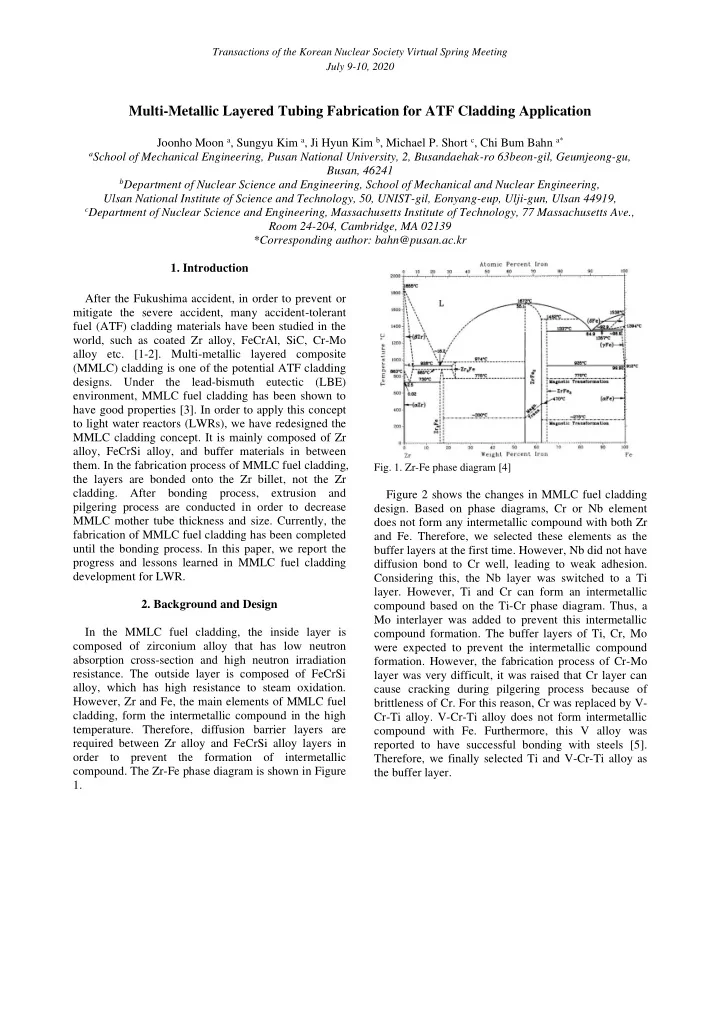
alloy, which has high resistance to steam oxidation. cause cracking during pilgering process because of However, Zr and Fe, the main elements of MMLC fuel brittleness of Cr. For this reason, Cr was replaced by V- cladding, form the intermetallic compound in the high Cr-Ti alloy. V-Cr-Ti alloy does not form intermetallic temperature. Therefore, diffusion barrier layers are compound with Fe. Furthermore, this V alloy was required between Zr alloy and FeCrSi alloy layers in reported to have successful bonding with steels [5]. order to prevent the formation of intermetallic Therefore, we finally selected Ti and V-Cr-Ti alloy as compound. The Zr-Fe phase diagram is shown in Figure the buffer layer. 1.

  2. Transactions of the Korean Nuclear Society Virtual Spring Meeting July 9-10, 2020 Fig. 4. Total process of small plate specimens During conducting the HIP process and heat treatment, these specimens were packed in the stainless steel case in order to prevent oxidation and increase bonding force. After HIP and heat treatment process, it was unpacked. The cold rolling process was Fig 2. Changes in MMLC fuel cladding design continuously conducted until cracks occurred in the specimens. 3. Fabrication & Evaluation of HIP Specimens 3.2. Evaluation results Before fabrication of the MMLC fuel cladding mother tube, in order to check any potential process In the case of 3-layer specimen, outermost layer was problems, small plate specimens were fabricated. Two broken when cold rolling it up to 1.6% thickness types of specimens were fabricated: 3-layer and 4-layer. reduction. On the other hand, in the case of 4-layer 3-layer specimen is consisted Zr alloy, Ti and specimen, the specimen shape was maintained when Fe12Cr2Si, whereas 4-layer specimen is consisted Zr cold rolling it up to 22% thickness reduction. In order to alloy, Ti, V and Fe12Cr2Si. Because the zircaloy-4 and check the chemical composition of layers, the SEM- V-Cr-Ti alloy of MMLC fuel cladding design were EDS analysis of each cross-section was conducted. difficult to obtain, small plate specimens were Figure 5 shows the overall shape and each layer’s fabricated using Zr 705 commercial alloy and pure V chemical composition of two specimens after the cold instead. Figure 3 shows the schematic of small plate rolling process. specimens. Fig. 5. Overall shape and each layer’s chemical composition of small plate specimens after cold rolling: (a) 3-layer, (b) 4- layer Fig. 3. Schematic of small plate specimens As shown in Figure 5, the top layer of 3-layer small 3.1. Fabrication and cold rolling plate specimen is a Zr-Ti-Fe intermetallic compound. This result indicates that the Ti single layer cannot be In order to bond materials, hot isostatic pressing an effective diffusion barrier. Also, the bottom Zr-Fe (HIP) process and heat treatment were used. After intermetallic compound is formed because of the bonding process, cold rolling was conducted in order to contact between Zr layer and stainless steel canning simulate the pilgering process of MMLC mother tube. materials. In the 4-layer small plate specimen, The total process of small plate specimens is shown in Fe12Cr2Si layer is still remained, and Zr-Fe Figure 4. intermetallic compound is not formed. It shows that the dual layers of Ti and V can prevent the formation of Zr- Fe intermetallic compound. Moreover, although some cracks occurred in Fe12CrSi layer after cold rolling, the overall specimen shape is maintained. Therefore, the

  3. Transactions of the Korean Nuclear Society Virtual Spring Meeting July 9-10, 2020 pilgering process is expected to be conducted well under suitable heat treatment conditions. 4. Fabrication & Evaluation of Mother Tube In the small plate specimen result, the Ti single layer could not prevent Zr-Fe intermetallic compound formation. However, if the Ti single layer is thick enough, it may be able to prevent the intermetallic compound formation. Also, the fewer the layers, the better the pilgering process. Therefore, two types of MMLC fuel cladding mother tube were fabricated: 3- layer and 4-layer. 3-layer mother tube has only the Ti single barrier layer, 4-layer mother tube has Ti and V- Cr-Ti dual barrier layers. The bonding process of MMLC mother tubes were conducted through the international collaboration. Fig. 7. EDS mapping and line-scan results on the cross- sectional images of 3-layer mother tube after HIP process 4.1. 3-layer MMLC mother tube Figure 7 shows some cracks in Fe12Cr2Si layer and In order to bond the materials, Zircaloy-4, Ti, forming of Zr-Ti-Fe intermetallic compound. This Fe12Cr2Si alloy were prepared. Fe12Cr2Si alloy was result shows that a thick Ti single layer cannot prevent made using overlay welding process on a carbon steel the formation of Zr-Fe intermetallic compound. It is the pipe. After building up the Fe12Cr2Si weld deposit same result as the HIP specimen. It is also observed that layer, the carbon steel pipe was removed. Each material the intermetallic layer actually consists of two different was bonded using a shrink-fit process. Figure 6 shows intermetallics: Zr-Ti and Zr-Ti-Fe, which seem to be the fabrication process and photographs of 3-layer separated in the intermetallic layer. Some small cracks mother tube. are also observed in this layer. However, it appears that the cracks of Fe12Cr2Si layer and intermetallic layer is not connected to each other, suggesting that two cracking phenomena occurred independently. The reason for the occurrence of some cracks in Fe12Cr2Si layer is under evaluation. 4.2. 4-layer MMLC mother tube In the 3-layer MMLC mother tube fabrication result, many cracks were observed after HIP process. Therefore, when making the 4-layer MMLC mother tube, the HIP process was removed. Other process is the same as the 3-layer MMLC mother tube. The 4-layer MMLC mother tube consists of zircaloy-4, Ti, V13Cr5Ti and Fe12Cr2Si alloy. Figure 8 shows the fabrication process and the assembled 4-layer mother tube. Fig. 6. Fabrication process and picture of 3-layer mother tube After the HIP process, it is observed that many cracks occurred in Fe12Cr2Si layer. In order to check the cause of cracking, the SEM-EDS analysis of cross- section was conducted. The EDS mapping result of 3- layer MMLC mother tube is shown in Figure 7.

Download Presentation
Download Policy: The content available on the website is offered to you 'AS IS' for your personal information and use only. It cannot be commercialized, licensed, or distributed on other websites without prior consent from the author. To download a presentation, simply click this link. If you encounter any difficulties during the download process, it's possible that the publisher has removed the file from their server.

Recommend


More recommend