limitations of fibre placement techniques for variable
play

LIMITATIONS OF FIBRE PLACEMENT TECHNIQUES FOR VARIABLE ANGLE TOW - PDF document

18 TH INTERNATIONAL CONFERENCE ON COMPOSITE MATERIALS LIMITATIONS OF FIBRE PLACEMENT TECHNIQUES FOR VARIABLE ANGLE TOW COMPOSITES AND THEIR PROCESS-INDUCED DEFECTS B.C. Kim 1 , K. Hazra 1 , P. Weaver 1 , K. Potter 1 * 1 ACCIS (Advanced Composite


  1. 18 TH INTERNATIONAL CONFERENCE ON COMPOSITE MATERIALS LIMITATIONS OF FIBRE PLACEMENT TECHNIQUES FOR VARIABLE ANGLE TOW COMPOSITES AND THEIR PROCESS-INDUCED DEFECTS B.C. Kim 1 , K. Hazra 1 , P. Weaver 1 , K. Potter 1 * 1 ACCIS (Advanced Composite Centre for Innovation and Science), University of Bristol, Queen’s Building, University Walk, Bristol BS8 1TR, UK * Corresponding author (K.Potter@bristol.ac.uk) shown in Table 1. Even if the tow element is a 1 Introduction perfect rectangle, the inner edge of the curved path The structural efficiency of composite panels with is necessarily buckled. When the imperfections of tailored fibre paths has attracted great attention in the tow element such as the difference of the edge recent decades. It was proved analytically that lengths and the width variation are introduced tailoring of the in-plane stiffness of composite additionally, the distortion of the tow element laminates can improve the buckling and post- becomes worse. In principle, the defects induced by buckling characteristics by redistributing the applied the in-plane bending deformation such as local loads [1-3] . Experimental research demonstrated its buckling and thickness change are unavoidable. It superior stiffness and buckling characteristic as well has, therefore, been recommended to keep a [4-5] . Currently, there is significant interest in minimum curvature of the tow path to reduce these developing methodologies to design optimal fibre local defects. orientations for maximizing the structural efficiency [6-8] . Case Deformed shape Defects The fibre placement technique is the core technology Local buckling Perfect underpinning variable stiffness composites. Typical Thickening condition analytical research does not model its underlying Thinning manufacturing limitations sufficiently. Some Local buckling researchers have tried to apply the process-induced Width Thickening defects such as the tow overlap and tow drop to the variation Thinning finite element analysis [9-11] . However, significant defects, to be considered in the analysis, still remain. Tension Local bending In this paper, realistic limitations of the current fibre variation Thinning placement techniques and their process-induced defects are investigated. Feed Local buckling length Thickening variation Thinning 2 Limitations of conventional techniques The automated fibre placement techniques can be Table 1. Tow deformation characteristics distinguished by the status of fibre. Pre-impregnated fibre bundles, i.e. towpreg or slittape, have widely been used previously [1] . Recently some researchers 2.2 Tow path definition and its limitation have attempted to use the dry fibre bundle to In defining tow paths, the parallel and shifted overcome the disadvantages of the tape placement methods have been used [10, 11] , as shown in Fig. 1. 
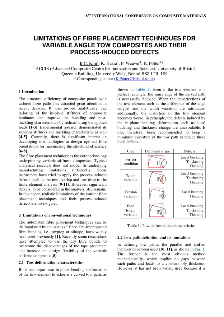
and increase the design flexibility of the variable The former is the most obvious method stiffness composite [5] . mathematically, which implies no gaps between 2.1 Tow deformation characteristics each paths and leads to a constant ply thickness. However, it has not been widely used because it is Both techniques use in-plane bending deformation of the tow element to achieve a curved tow path, as

  2. not easy to manufacture the tow-steered plate with a large stiffness by using it. Tow overlap The shifted method is a more efficient way to make the variable-stiffness plate. However, the width of a tow is dependent on the applicator head that has a finite width. Rotation of the head leads to a realignment of fibres within a tow parallel to the Tow gap centerline of the tow path, which creates overlapped Tow path line regions and gaps between two adjacent tows [10, 11] . Edge of the tow Though several methods such as staggering, tow Fig. 2. Comparison between fibre and tow paths overlap and tow drop techniques have been following the shifting method. developed to solve this problem [10, 11] , there still remain some tow path configurations where the resin rich areas are not covered. In terms of the fibre trajectory, the conventional 3.1 Tape placement shifting method is a sort of mixed method because Generally the automatic fibre placement (AFP) paths of each single fibre within a tow are always machine uses the pre-impregnated tow tape which is parallel due to the head rotation, which inevitably called towpreg or slittape. In the case of the tow requires tow gap or overlap region to fill the space placement process using tapes, since the width of the between two tow paths, as shown in Fig. 2. As the pre-impregnated tow bundle cannot be easily curvature of the tow path increases, the area of tow changed, tow drop and overlap techniques should be gap or overlap increases. If the fibre orientation applied to prevent a significant thickness change and needs to be straight in some area as shown in Fig. 1 cover the resin rich area. Tow drop introduces many (a), every tow in that area should be overlapped to fibre discontinuities which may affect the cover the tow gap around the curved path. Otherwise, mechanical performance. In addition, when the cut localized large tow gap area can be created. This is tape laid by the compaction roller loses tension, the worst case which can happen when the unwanted geodesic tow paths can be produced [13] . conventional shifting method is used with the In many cases, the AFP machine lays multiple tows conventional machine using a rotational head motion. simultaneously to improve the productivity [9, 13] . As illustrated in Fig. 3, the main disadvantage of this 3 Process-induced defects method is that the mismatch between designed and real fibre paths increases as the width of a single tow In addition to the local fibre buckling induced by in- and the number of tows laid at the same time plane bending deformation, defects caused by the increase. This always requires the sacrifice of process characteristics of each tow placement uniformity of the fibre orientation, some defects method also exist. such as tow gap and overlap and irregularity of the thickness distribution, which consequently causes another mismatch with the analytical solution. Because of this non-uniformity of the fibre orientation and thickness distribution, a complex program creating finite elements which can take all imperfection into account is required for accurate structural analysis [9-11] . All these problems are caused by the mixed method which has been called a ‘shifting method’ previously. (a) (b) The negative effects of these defects were already Fig. 1. Definition of tow paths: (a) parallel method, proved through experiments. It was reported that the (b) shifting method. structural strength of the variable stiffness panel with tow drop was considerably lower than that with

  3. LIMITATIONS OF FIBRE PLACEMENT TECHNIQUES FOR VARIABLE ANGLE TOW COMPOSITES AND THEIR PROCESS—INDUCED DEFECTS tow overlap although the specific structural Stitching yarn Tow stiffnesses of them were similar [4] . It was also Backup fabric revealed that the in-plane shear strength decreased 1 2 significantly when the tow overlap exists along the Backup perpendicular direction to the loading direction [14] . felt < Cross-section view > 3.2 Dry tow placement Fibre wrinkle induced Stitching yarn Some researchers have attempted to overcome the by in-plane bending Ideal tow boundary disadvantages of the tape placement technique by using dry tow because it is much easier to bend or 2 sheared [5, 15] . The advantage of this method is that the finished preform can be kept at room temperature with unlimited shelf life. Also, dry tows and resin purchased individually are significantly 1 cheaper than the towpreg or slittape produced. < Top view > Although the dry tow placement method can also Fig. 4. Ideal tow deformation during the embroidery introduce a mismatch between designed and real process. fibre paths as illustrated in Fig. 2, it can be diluted by the rearrangement of fibres within the dry tow. However, the improved design flexibility causes Stitching yarn Tow Backup fabric other types of process-induced defects which are quite different from those of the tape placement 1 2 techniques besides local defects induced by the in- Backup felt plane bending deformation previously mentioned. < Cross-section view > Because dry tow does not have tackiness, it can’t be laid without a proper fixing method. The most Fibre wrinkle induced widely used method is an embroidery technique in Stitching yarn by in-plane bending Ideal tow boundary which the numerically controlled stitching head Non-uniform stitches tows with any type of thread to hold the tow tension preform shape together onto a backup fabric [5, 15] . 2 Additional backup felt is generally used to reinforce the backup fabric. And, resin film infusion (RFI) is used to impregnate the preform. 1 Tow gap Designed tow path Edge of each tow < Top view > Fig. 5. Real tow deformation during the embroidery Tow gap process. Fig. 4 shows the ideal tow deformation when Tow overlap assuming the tow fixing is perfect. Even for this case, local buckling of the fibres inside the curved tow path is induced by the in-plane bending deformation. However, the real deformation of the tow introduces more complex types of process-induced defects, as (a) (b) shown in Fig. 5. Because the fabric may be wrinkled Fig. 3. Multiple tow laying using the conventional if the tension of the stitching yarn is too high and the AFP machine: Tow drop (left), Tow overlap (right). softness of the backup felt allows the stitching yarn 3

Download Presentation
Download Policy: The content available on the website is offered to you 'AS IS' for your personal information and use only. It cannot be commercialized, licensed, or distributed on other websites without prior consent from the author. To download a presentation, simply click this link. If you encounter any difficulties during the download process, it's possible that the publisher has removed the file from their server.

Recommend


More recommend