Lecture no: 8 051 Inter-symbol interference Linear equalizers - - PowerPoint PPT Presentation

lecture no 8
SMART_READER_LITE
LIVE PREVIEW

Lecture no: 8 051 Inter-symbol interference Linear equalizers - - PowerPoint PPT Presentation

RADIO SYSTEMS ETI Contents Lecture no: 8 051 Inter-symbol interference Linear equalizers Decision-feedback equalizers Maximum-likelihood sequence estimation Equalization Ove Edfors, Department of Electrical and


slide-1
SLIDE 1

Ove Edfors, Department of Electrical and Information Technology Ove.Edfors@eit.lth.se

RADIO SYSTEMS – ETI 051

Lecture no: 8

Equalization

2010-04-29 Ove Edfors - ETI 051 2

Contents

  • Inter-symbol interference
  • Linear equalizers
  • Decision-feedback equalizers
  • Maximum-likelihood sequence estimation

2010-04-29 Ove Edfors - ETI 051 3

INTER-SYMBOL INTERFERENCE

2010-04-29 Ove Edfors - ETI 051 4

Inter-symbol interference Background

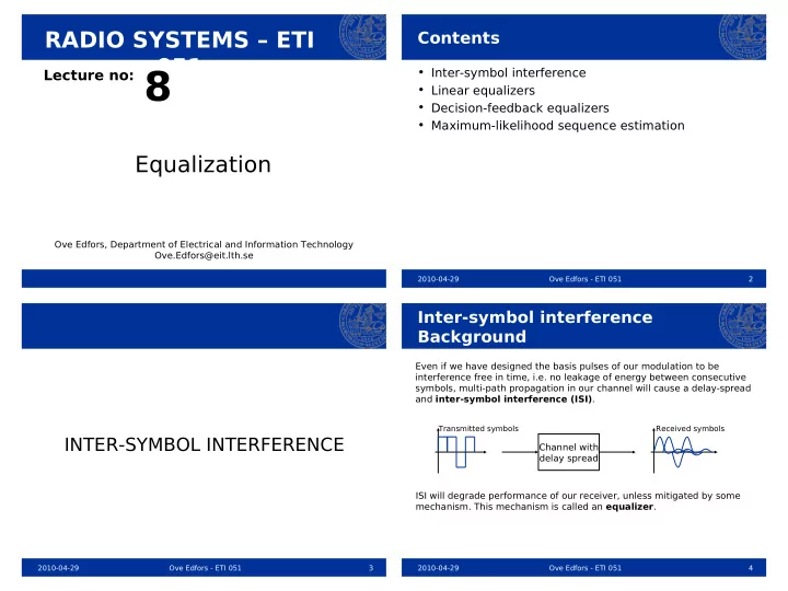
Even if we have designed the basis pulses of our modulation to be interference free in time, i.e. no leakage of energy between consecutive symbols, multi-path propagation in our channel will cause a delay-spread and inter-symbol interference (ISI). ISI will degrade performance of our receiver, unless mitigated by some

  • mechanism. This mechanism is called an equalizer.

Transmitted symbols

Channel with delay spread

Received symbols

slide-2
SLIDE 2

2010-04-29 Ove Edfors - ETI 051 5

Inter-symbol interference Including a channel impulse response

( )

*

g T t −

( )

n t ( )

g t

PAM Matched filter What we have used so far (PAM and optimal receiver): Including a channel impulse response h(t):

( )

n t ( )

g t

( )

k

c t kT δ − kT PAM Matched filter

k

ϕ ( )

h t ?

This one is no longer ISI-free and noise is not white ISI-free and white noise with proper pulses g(t) Can be seen as a “new” basis pulse ( )

k

c t kT δ − kT

k

ϕ

g∗h

∗T −t

2010-04-29 Ove Edfors - ETI 051 6

Inter-symbol interference Including a channel impulse response

We can create a discrete time equivalent of the “new” system:

k

n

k

c

k

ϕ ( )

1

* F z−

( )

F z

where we can say that F(z) represent the basis pulse and channel, while F*(z -1) represent the matched filter. (This is an abuse of signal theory!) ( )

1

1/ * F z−

Noise whitening filter

k

n

k

c

k

ϕ ( )

1

* F z−

( )

F z

We can now achieve white noise quite easily, if (the not unique) F(z) is chosen wisely (F*(z -

1) has a stable inverse) : k

u

NOTE: F*(z -1)/F *(z -1)=1 2010-04-29 Ove Edfors - ETI 051 7

Inter-symbol interference The discrete-time channel model

With the application of a noise-whitening filter, we arrive at a discrete-time model

k

n

k

c

k

u ( )

F z

where we have ISI and white additive noise, in the form The coefficients f j represent the causal impulse response of the discrete-time equivalent of the channel F(z), with an ISI that extends

  • ver L symbols.

This is the model we are going to use when designing equalizers.

uk=∑

j=0 L

f j ck− jnk

2010-04-29 Ove Edfors - ETI 051 8

LINEAR EQUALIZER

slide-3
SLIDE 3

2010-04-29 Ove Edfors - ETI 051 9

Linear equalizer Principle

k

n

k

c

k

u ( )

F z

The principle of a linear equalizer is very simple: Apply a filter E(z) at the receiver, mitigating the effect of ISI: ( )

E z

k

c $ Linear equalizer Now we have two different strategies: 1) Design E(z) so that the ISI is totally removed 2) Design E(z) so that we minimize the mean squared-error of

k k k

c c ε = − $

Zero-forcing MSE

2010-04-29 Ove Edfors - ETI 051 10

Linear equalizer Zero-forcing equalizer

k

n

k

c

k

u ( )

F z

( )

1/ F z

k

c $

ZF equalizer

The zero-forcing equalizer is designed to remove the ISI completely f

FREQUENCY DOMAIN Information

f

Channel

f

Noise

f

Equalizer

f

Information and noise Noise enhancement!

2010-04-29 Ove Edfors - ETI 051 11

Linear equalizer Zero-forcing equalizer, cont.

A serious problem with the zero-forcing equalizer is the noise enhancement, which can result in infinite noise power spectral densities after the equalizer. The noise is enhanced (amplified) at frequencies where the channel has a high attenuation. Another, related, problem is that the resulting noise is colored, which makes an optimal detector quite complicated. By applying the minimum mean squared-error criterion instead, we can at least remove some of these unwanted effects.

2010-04-29 Ove Edfors - ETI 051 12

Linear equalizer MSE equalizer

k

n

k

c

k

u ( )

F z

k

c $

MSE equalizer

The MSE equalizer is designed to minimize the error variance f

FREQUENCY DOMAIN Information

f

Channel

f

Noise Less noise enhancement than Z-F!

( )

( )

2 * 1 2 2 s s

F z F z N σ σ

+

f

Equalizer

f

Information and noise

slide-4
SLIDE 4

2010-04-29 Ove Edfors - ETI 051 13

Linear equalizer MSE equalizer, cont.

The MSE equalizer removes the most problematic noise enhancements as compared to the ZF equalizer. The noise power spectral density cannot go to infinity any more. This improvement from a noise perspective comes at the cost of not totally removing the ISI. The noise is still colored after the MSE equalizer which, in combination with the residual ISI, makes an optimal detector quite complicated.

2010-04-29 Ove Edfors - ETI 051 14

DECISION-FEEDBACK EQUALIZER

2010-04-29 Ove Edfors - ETI 051 15

Decision-feedback equalizer Principle

We have seen that taking care of the ISI using only a linear filter will cause (sometimes severe) noise coloring. A slightly more sophisticated approach is to subtract the interference caused by already detected data (symbols). This principle of detecting symbols and using feedback to remove the ISI they cause (before detecting the next symbol), is called decision- feedback equalization (DFE).

2010-04-29 Ove Edfors - ETI 051 16 This part removes ISI on “future” symbols from the currently detected symbol. This part shapes the signal to work well with the decision feedback.

Decision-feedback equalizer Principle, cont.

k

n

k

c ( )

F z

( )

E z Forward filter

( )

D z Feedback filter

k

c $

Decision device

If we make a wrong decision here, we may increase the ISI instead

  • f remove

it.

+

slide-5
SLIDE 5

2010-04-29 Ove Edfors - ETI 051 17

Decision-feedback equalizer Zero-forcing DFE

In the design of a ZF-DFE, we want to completely remove all ISI before the detection.

k

n

k

c ( )

F z

( )

E z

( )

D z

k

c $ ISI-free

+

  • This enforces a relation between the E(z) and D(z), which is (we assume

that we make correct decisions!)

( ) ( ) ( )

1 F z E z D z − =

As soon as we have chosen E(z), we can determine D(z). (See textbook for details!)

2010-04-29 Ove Edfors - ETI 051 18

Decision-feedback equalizer Zero-forcing DFE, cont.

Like in the linear ZF equalizer, forcing the ISI to zero before the decision device of the DFE will cause noise enhancement. Noise enhancement can lead to high probabilities for making the wrong decisions ... which in turn can cause error propagation, since we may add ISI instead of removing it in the decision-feedback loop. Due to the noise color, an optimal decision device is quite complex and causes a delay that we cannot afford, since we need them immediately in the feedback loop.

2010-04-29 Ove Edfors - ETI 051 19

Decision-feedback equalizer MSE-DFE

k

n

k

c ( )

F z

( )

E z

( )

D z

k

c $ minimal MSE

+

  • To limit noise enhancement problems, we can concentrate on minimizing

mean squared-error (MSE) before the decision device instead of totally removing the ISI. The overall strategy for minimizing the MSE is the same as for the linear MSE equalizer (again assuming that we make correct decisions). (See textbook for details!)

2010-04-29 Ove Edfors - ETI 051 20

Decision-feedback equalizer MSE-DFE, cont.

By concentrating on minimal MSE before the detector, we can reduce the noise enhancements in the MSE-DFE, as compared to the ZF-DFE. By concentrating on minimal MSE before the detector, we can reduce the noise enhancements in the MSE-DFE, as compared to the ZF-DFE. The performance of the MSE-DFE equalizer is (in most cases) higher than the previous equalizers ... but we still have the error propagation problem that can occur if we make an incorrect decision.

slide-6
SLIDE 6

2010-04-29 Ove Edfors - ETI 051 21

MAXIMUM-LIKELIHOOD SEQUENCE ESTIMATION

2010-04-29 Ove Edfors - ETI 051 22

Maximum-likelihood sequence est. Principle

The optimal equalizer, in the sense that it with the highest probability correctly detects the transmitted sequence is the maximum-likelihood sequence estimator (MLSE). The principle is the same as for the optimal symbol detector (receiver) we discussed during Lecture 7, but with the difference that we now look at the entire sequence of transmitted symbols.

k

n

k

c

k

u ( )

F z

MLSE: Compare the received noisy sequence uk with all possible noise free received sequences and select the closest one!

k

c $ For sequences of length N bits, this requires comparison with 2N different noise free sequences.

2010-04-29 Ove Edfors - ETI 051 23

Maximum-likelihood sequence est. Principle, cont.

Since we know the L+1 tap impulse response f j , j = 0, 1, ... , L, of the channel, the receiver can, given a sequence of symbols {cm}, create the corresponding “noise free signal alternative” as where NF denotes Noise Free. The MLSE decision is then the sequence of symbols {cm} minimizing this distance

{ 

cm}=arg min

{cm}

∑m∣um−∑ j=0

L

f jcm− j∣

2

The squared Euclidean distance (optimal for white Gaussian noise) to the received sequence {um} is

d

2{um},{um NF}=∑ m ∣um−um NF∣ 2=∑ m ∣um−∑ j=0 L

f jcm− j∣

2

um

NF=∑ j=0 L

f j cm− j

2010-04-29 Ove Edfors - ETI 051 24

Maximum-likelihood sequence est. Principle, cont.

This equalizer seems over-complicated and too complex. The discrete-time channel F(z) is very similar to the convolution encoder discussed during Lecture 7 (but with here complex input/output and rate 1):

k

c

( )

F z

1

z−

1

z−

1

z−

f

1

f

2

f

L

f

We can build a trellis and use the Viterbi algorithm to efficiently calculate the best path!

Filter length L+1 has memory L.

slide-7
SLIDE 7

2010-04-29 Ove Edfors - ETI 051 25

Maximum-likelihood sequence est. The Viterbi-equalizer

Let’s use an example to describe the Viterbi-equalizer. Discrete-time channel: Further, assume that our symbol alphabet is –1 and +1 (representing the bits 0 and 1, respectively).

1

z−

k

c

  • 0.9

f

( )

2

F z

This would cause serious noise enhancement in linear equalizers.

The fundamental trellis stage: State

  • 1

1

1.9

  • 0.1
  • 1.9

Input cm

  • 1

+1

0.1 2010-04-29 Ove Edfors - ETI 051 26

Detected sequence: 1 1 -1 1 -1 State

  • 1

1 VITERBI DETECTOR

1.9

  • 0.1
  • 0.1
  • 1.9

1.9

  • 0.1
  • 1.9

0.1 1.9

  • 0.1
  • 1.9

0.1 1.9

  • 0.1
  • 1.9

0.1 1.9 0.1

Maximum-likelihood sequence est. The Viterbi-equalizer, cont.

0.76 5.75 3.60 1.40 0.68 1.39 3.32 1.44 13.72 4.64 2.86 13.58 2.09 5.62

Transmitted: 1 1 -1 1 -1

1

1 0.9z− −

Noise Noise free sequence: 1.9 0.1 -1.9 1.9 -1.9

Received noisy sequence: 0.72 0.19 -1.70 1.09 -1.06

3.78 2.79 11.62 3.43

At this stage, the path ending here has the best metric! The filter starts in state –1.

Correct!

2010-04-29 Ove Edfors - ETI 051 27

Maximum-likelihood sequence est. The Viterbi-equalizer, cont.

The Viterbi-equalizer (detector) is optimal in terms of minimizing the probability of detecting the wrong sequence of symbols. For transmitted sequences of length N over a length L+1 channel, it reduces the brute-force maximum-likelihood detection complexity of 2N comparisons to N stages of 2L comparisons through elimination of trellis paths. L is typically MUCH SMALLER than N. Even if it reduces the complexity considerably (compared to brut-force ML) it can have a too high complexity for practical implementations if the length

  • f the channel (ISI) is large.

2010-04-29 Ove Edfors - ETI 051 28

Some final thoughts

We have not covered the topic of channel estimation, which is required since the equalizers need to know the channel. (See textbook for details!) In practice, a channel estimate will never be exact. This means that equalizers in reality are never optimal in that sense. The channel estimation problem becomes more problematic in a fading environment, where the channel constantly changes. This requires good channel estimators that can follow the changes of the channel so that the equalizer can be updated continuously. This can be a very demanding task, requireing high processing power and special training sequences transmitted that allow the channel to be estimated. In GSM there is a known training sequence transmitted in every burst, which is used to estimate the channel so that a Viterbi-equalizer can be used to remove ISI.

slide-8
SLIDE 8

2010-04-29 Ove Edfors - ETI 051 29

Summary

  • Linear equalizers suffer from noise enhancement.
  • Decision-feedback equalizers (DFEs) use decisions
  • n data to remove parts of the ISI, allowing the linear

equalizer part to be less ”powerful” and thereby suffer less from noise enhancement.

  • Incorrect decisions can cause error-propagation in

DFEs, since an incorrect decision may add ISI instead of removing it.

  • Maximum-likelihood sequence estimation (MLSE)

is optimal in the sense of having the lowest probability

  • f detecting the wrong sequence.
  • Brute-force MLSE is prohibitively complex.
  • The Viterbi-eualizer (detector) implements the MLSE

with considerably lower complexity.