
1
Intro to Camera Models
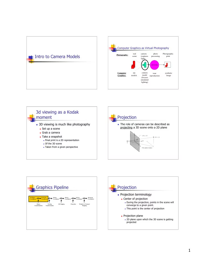
Computer Graphics as Virtual Photography
camera (captures light) synthetic image camera model (focuses simulated lighting)
processing
photo processing tone reproduction real scene 3D models Photography: Computer Graphics: Photographic print
3d viewing as a Kodak moment
3D viewing is much like photography
Set up a scene Grab a camera Take a snapshot
Final print is a 2D representation Of the 3D scene Taken from a given perspective
Projection
The role of cameras can be described as
projecting a 3D scene onto a 2D plane
Graphics Pipeline
3D Object Coordinates 3D World Coordinates 3D Eye Coordinates 3D Eye Coordinates 2D Eye Coordinates 2D Screen Coordinates Object Transformation Viewing Transformation 3D Clipping Projection Window to Viewport Mapping
Projection
Projection terminology
Center of projection
During the projection, points in the scene will
converge to a given point.
This point is the center of projection
Projection plane
2D plane upon which the 3D scene is getting