Inno novati tive e Biologi logica cal l Emissions ssions - - PowerPoint PPT Presentation

inno novati tive e biologi logica cal l emissions ssions
SMART_READER_LITE
LIVE PREVIEW

Inno novati tive e Biologi logica cal l Emissions ssions - - PowerPoint PPT Presentation

1/31/2017 Kim Jones, David Ramirez , Shooka Khoramfar Department of Environmental Engineering, Texas A&M University-Kingsville, Kingsville, TX 78363, USA Project consultant: James Boswell, Boswell Environmental, Montgomery, Texas Project


slide-1
SLIDE 1

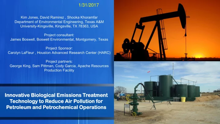
Inno novati tive e Biologi logica cal l Emissions ssions Treatmen ment t Technolo nology gy to Reduce e Air Poll llutio ution n for Petroleu

  • leum and Petroc
  • che

hemic mical al Operati tions

  • ns

Kim Jones, David Ramirez , Shooka Khoramfar Department of Environmental Engineering, Texas A&M University-Kingsville, Kingsville, TX 78363, USA Project consultant: James Boswell, Boswell Environmental, Montgomery, Texas Project Sponsor: Carolyn LaFleur , Houston Advanced Research Center (HARC) Project partners: George King, Sam Pittman, Cody Garcia, Apache Resources Production Facility

1/31/2017

slide-2
SLIDE 2

Potential opportunities for biological air emission control

2

Waste Water during Drilling, Fracturing and Natural Gas Production Process equipment such as Compressors and motors on the drilling and production sites Condensate storage tanks

Based on Occupational Safety and Health Administration (OSHA), permissible exposure limit (PEL) (8 h TWA) of benzene for general industry = 1.0 ppm

slide-3
SLIDE 3

Why biological treatment?

  • Biological treatment of air emissions offers a cost-effective and sustainable control

technology for industrial facilities facing increasingly stringent air emissions limits.

  • This system uses the capacity of microorganisms to degrade air toxins (HAPs,

Hazardous Air Pollutants), like benzene without the use of natural gas as fuel or the creation of secondary pollutants.

  • The replacement of conventional thermal oxidizers with biofilters will yield natural

gas savings alone in the range of thousands of dollars to over $1 million per year per unit.

  • Any new technology that could replace a single thermal oxidizer (100,000cfm size)

could provide a savings of more than 4,166 MM BTUs of natural gas annually (based

  • n 8,760 hrs of operation and 0.475 MM BTU per hour of usage). That represents

enough natural gas to comfortably heat or cool approximately 120 homes annually for each thermal oxidizer or flare replaced.

  • Water vapor, carbon dioxide and biomass are the products of aerobic biodegradation
  • f organic pollutants. However, the carbon emissions in biologically based units is

much less than incinerators and flares.

3

(Source: Boswell, 2008)

slide-4
SLIDE 4

Successful pilot scale sequential treatment for VOC emissions at different industries

4

Forest product plant, Stimson Lumber Co. Gaston, Oregon Paint & Coatings Eugene, Oregon

slide-5
SLIDE 5

Process description

  • The goal of this project is to demonstrate a novel sequential treatment technology that integrates two

types of bio-oxidation systems biotrickling filter and fixed bed biofilter for controlling petrochemical industries air emissions.

  • This coupled design can be optimized to maximize the conditions for microbial degradation of VOC

vapors.

  • The first bed takes the highest inlet VOC loadings, to remove the more water soluble organics, while

the secondary bed acts as an overload and polishing stage to remove more complex organic compounds.

  • The first unit also controls the incoming air stream temperature and regulates humidity and dampens

fluctuations in contaminant loadings.

  • Less hydrophobic pollutants can be removed in the first stage Bio-trickling Chamber by the biofilm on

the surfaces of the X-Flow media and microbes in the sump and more hydrophobic compounds should be removed within the Bio-Matrix Chamber periodically sprayed with sump water to maintain proper moisture for best biofilm development.

  • Water entering the biotrickling filter is collected in a sump, monitored for water quality parameters,

and continuously sprayed onto the top of the X-flow media bed in the BTF.

  • The flowing water phase benefits the biotrickling filter by providing a continuous supply of nutrients,

removing possible degradation by-products, suspending biomass for continual reseeding of the system, and aiding in the transfer of hydrophilic pollutants onto the biofilm.

5

slide-6
SLIDE 6

Objectives for the Apache (TAMU #2 tank battery) field test

Sampling and characterization of some field VOCs emissions

1

Design, build, process test and implementation of a field scale sequential treatment unit in 12 months

2

Demonstrate the ability of bio-oxidation systems to treat variable loadings of VOC emissions as experienced in refineries and production facilities during routine operations, process turnarounds or upsets

3

Optimize the process for the ability to efficiently degrade mixtures of hydrophobic compounds typically encountered in refinery and oil and gas production facility emissions

4

6

slide-7
SLIDE 7

Characterization of VOCs

7

GC-FID PID GC-MS

slide-8
SLIDE 8

Biotrickle filter media (First vessel)

8

slide-9
SLIDE 9

Biofilter media (Second vessel)

9

slide-10
SLIDE 10

Key design and operational parameters

10

Key design and

  • perational

parameters

Air flow rate Water flow rate Temperature pH and Conductivity Nutrient concentration Pressure Biofilter bed moisture

slide-11
SLIDE 11

Field scale unit start up at Apache TAMU #2 tank battery- 10 May 2016 to 1 August 2016

11

The field unit consists of a skid mounted two vessel system (100 cubic feet of total treatment volume) made of fiberglass with corrosion resistant schedule 80 PVC piping (Diamond Fiberglass Fabricator, Victoria, TX).

slide-12
SLIDE 12

Field scale unit start up at Apache TAMU #2 tank battery- 6 May 2016

12

slide-13
SLIDE 13

Date Completed task 04/28/16  Load the BF media to the second vessel 05/05/16- 05/25/16  Safety meeting,  Generator set up,  Sampled of the headspace for GC-MS analysis,  Loaded the BTF media to the first vessel,  Checked the immediate area around the system for hydrocarbon content with a photoionization detector (PID),  Inoculation of the system with oily water and compost tea,  Checked the water pump and blower performance 05/30/16  Inoculation of the system with the CITGO’s Corpus Christi Refinery wastewater

13

Field scale unit start up at Apache TAMU #2 tank battery- 28 April 2016 to 30 May 2016-

slide-14
SLIDE 14

Main dimensions and characteristics of the two tanks

BTF BF

Bed height (ft)

4 4

Diameter (ft)

4 4

Ratio height to diameter

1 1

Recirculation tank volume (gal) 100

100

Water make-up tank volume (gal)

300

Air flow rate (ft3/min)

25 25

Recirculation flow rate (gal/min)

3.5 (optimization possible) 3.5 (optimization possible)

Spraying frequency

24/7 2 min every 8 hr (optimization possible)

Gas velocity, (ft/min)

300 300

EBRT (min)

2 (optimization possible) 2 (optimization possible)

14

slide-15
SLIDE 15

GC-MS characterization from the headspace of the Apache TAMU #2 tank battery

15

Peak # Component Retention Time

  • Conc. (ppm)

1

Butane

9.51 6709

2

Isobutane

9.21 5118

3

Pentane

10.88 4233

4

Butane, 2-methyl-

10.45 4189

5

Hexane

13.03 1553

6

Pentane, 2-methyl-

12.29 1497

7

Cyclohexane, methyl-

16.16 896

8

Heptane

15.50 649

9

Cyclopentane, methyl-

13.75 534

10

Toluene

16.93 282

11

Octane

17.83 218

12

Benzene

14.32 197

13

Nonane

19.90 110

14

p-Xylene

19.22 87

slide-16
SLIDE 16

Fluctuation in VOC concentration at inlet of the bio-oxidation unit – 1 August 2016- Apache TAMU #2 tank battery

200 400 600 800 1000 1200

8:24 AM 9:36 AM 10:48 AM 12:00 PM 1:12 PM 2:24 PM 3:36 PM

VOC (ppm isobutylene equivalent)

Time

16

slide-17
SLIDE 17

PID measurements from the inlet and outlet of the bio-oxidation unit- 10 May 2016 to 29 July 2016- Apache TAMU #2 tank battery

17

100 200 300 400 500 600 700 800 900 1000 10-May 20-May 30-May 9-Jun 19-Jun 29-Jun 9-Jul 19-Jul 29-Jul

VOC (ppm isobutylene equivalent)

Time

Inlet Outlet

slide-18
SLIDE 18

Removal efficiency of the biooxidation unit- 10 May 2016 to 29 July 2016- Apache TAMU #2 tank battery

18

0% 10% 20% 30% 40% 50% 60% 70% 10-May 20-May 30-May 9-Jun 19-Jun 29-Jun 9-Jul 19-Jul 29-Jul

RE (%) Time

BTF removal efficiency Overall removal efficiency BF removal efficiency

Average RE of the system (July month): 53% Average RE of the BTF (July month): 40% Average RE of the BF (July month): 23%

slide-19
SLIDE 19

Performance characteristics of the BTF unit using GC- FID- Sampling at 28 July using 3 tedlar bags

Compound Retention time (min) Inlet concentration (ppm) Outlet concentration (ppm) RE (%) p-Xylene 1.57 587 228 61%

  • -Xylene

4.44 498 322 35% Benzene 6.41 44 31 30%

19

slide-20
SLIDE 20

Biofiltration Summary

  • In spite of the hydrophobic nature of the pollutants, a relatively high

VOC removal was observed in the BTF unit probably due to high biofilm growth and continuous spraying of water and nutrients.

  • BF watering is an important operational parameter since it directly

influences the water content and the pH value on the filter media. At the Apache site, given the very warm temperatures during the field biofiltration test, increased irrigation of the BF unit was probably needed.

  • The surprisingly high VOC removal capabilities of the BTF unit suggests

that a combination of both suspended growth and attached growth biofilms may provide an important new approach toward biotreatment

  • ptimization of VOCs for the oil and gas and petrochemical industries
  • The bio-technology employed in this project may be a cost-effective

treatment technique to mitigate VOC emissions from oil and gas facilities and should be evaluated as a possible MACT (Maximum Achievable Control Technology) to control HAPs.

20

slide-21
SLIDE 21

Next steps…

  • To improve the removal efficiency in the bio-oxidation unit, water

addition to the system (BTF and BF) should be optimized along with the nutrients concentration.

1. Collecting media samples periodically in order to measure moisture and nutrient concentration of the compost media according to standard methods. 2. Periodically, monitoring pH, conductivity and nutrient (ammonia, nitrate nitrogen, total phosphorus) concentration of the sump.

  • Since the air flow rate or empty bed residence time (e.g. the size of

the unit, etc.) will obviously affect the treatment costs, the bio-

  • xidation performance will be optimized under various operation

conditions.

  • To improve the removal efficiency in the BTF unit for hydrophobic

pollutants, addition of surfactants may be tested.

21

slide-22
SLIDE 22

Implementation of Air Quality Technology for the Oil and Gas Industry in Coastal Areas: Air Emission Measurements and Control

Contract No. CITP0910-TAMUK0513B Coastal Impact Assistance Program Investigator: Dr. David Ramirez

slide-23
SLIDE 23

Current Practice Proposed TSA System

23

Project Goal

The development and testing of a thermal-swing adsorption (TSA) system to capture and recover toxic air emissions from point sources (storage condensate tanks)

slide-24
SLIDE 24

24

Design and Development of TSA System: Phase I – Bench Scale

slide-25
SLIDE 25

Summary Benzene Toluene Ethyl benzene m, p- Xylene

  • -Xylene

Average 138 136 0.440 31.8 4.73 Maximum 575 306 11.9 95.0 10.6 Minimum 112 109 1.17 3.31 4.32

25

Summary of BTEX Concentrations (ppm) from Bench Scale Condensate Tank with Sample API, 54.2

0.00 0.02 0.04 0.06 0.08 0.10 0.12 0.14

Benzene Toluene Ethylbenzene m, p-Xylene

  • -Xylene

Xylene (m, p and o)

BTEX Emission Rate (lb/yr) Experiment Tank 4.09d Promax 3.2

Comparison of Experimental BTEX Emissions with Simulations from Promax 3.2 and Tanks 4.09D

slide-26
SLIDE 26

Recovered liquid hydrocarbons at regeneration temperatures between 80-125°C

26

(80-90)°C (105-125)°C

Effect of Regeneration Temperature on the Liquid Recovery

slide-27
SLIDE 27

27

Phase II of the TSA System: Pilot Scale

Schematic of the 100 sLpm-Capacity Pilot Scale TSA System

slide-28
SLIDE 28

28

Phase III of the TSA System: the 3,000 sLpm Pilot Scale Unit

Pilot Scale TSA System for Continuous Operation

slide-29
SLIDE 29

29

Phase III of the TSA System: Field Deployment

  • f the 3,000 sLpm Pilot Scale Unit

Field testing at the Apache site for capturing vapor emissions from the tank battery

slide-30
SLIDE 30

Operation Conditions and Removal Efficiencies for the Pilot-Scale TSA Unit During the Field Test

30

200 400 600 800 1000 100 200 300 Total Hydrocarbon Concentration (ppmv) Time (min) Inlet concentration Outlet concentration

Adsorption Column 1

Parameter Value Gas stream temperature 110°F Gas volumetric flow rate 142 sLpm Amount of granular activated carbon in adsorption column 1 5 kg Amount of granular activated carbon in adsorption column 2 8 kg Removal efficiency of total hydrocarbons before breakthrough

99.6%

Removal efficiency of H2S 100% Removal efficiency of CO2 96.3%

slide-31
SLIDE 31

Adsorption Breakthrough for the Pilot-Scale TSA Unit During the Field Test: Adsorption Column 2

31

200 400 600 800 1000 50 100 150 200 250 300

Total Hydrocarbon Concentration (ppmv) Time (min) Inlet concentration Outlet concentration

slide-32
SLIDE 32

Next steps…

  • The field deployable GC-FID will be used along with the PIDs in order to

continuously monitor the concentration of BTEX compounds in the gas phase.

  • We would welcome more opportunities to work with Apache/HARC to
  • ptimize our field scale unit for removal of BTEX compounds.

32

Subsequent phases of this project would be optimization of air flow, water flow and residence time for the most effective BTEX degradation for remote oil and gas facilities, and the deployment of more telemetry and modem communication, with a Programmable Logic Controller (PLC) to remotely monitor unit performance and operating conditions.

slide-33
SLIDE 33

Acknowledgements

  • This project was funded by the Houston Advanced Research

Center’s (HARC) Environmentally Friendly Drilling - Coastal Impacts Technology Program GLO Contract #M11AF00005

  • Apache Corporation, Houston and Bryan/College Station, Texas
  • Institute for Sustainable Energy and the Environment
  • Texas A&M University-Kingsville (TAMUK)
  • TAMUK team of students
  • Shooka Khoramfar
  • Joshua Robbins
  • Fasae Olusola
  • Erich Potthast
  • Josie Rios

33

slide-34
SLIDE 34

34

The environmental crisis is a global problem, and only global action will resolve it. ~ Barry Commoner, biologist

Thank you for your attention!

slide-35
SLIDE 35

35

slide-36
SLIDE 36

Mit itig igation of Vapor Emis issions

  • Source reduction
  • Modifying process
  • Thermal combustion
  • Flaring
  • Catalytic incineration
  • Biofiltration
  • Condensation
  • Membrane separation
  • Absorption
  • Adsorption

36

Destructive Methods Recovery Methods Preventive Methods

slide-37
SLIDE 37

Storage Tank Emissions

  • Oil and condensate tanks are

used to store produced liquid at individual well sites.

  • Two primary emission loss are:
  • Flashing loss, condensate

brought from down hole pressure to atmospheric pressure may experience a sudden volatilization

  • f some of the condensate
  • Working and breathing losses,

whereby some volatilization of stored product occurs through valves and other openings in the tank battery over time. (TCEQ,2010)

37

Oil and Condensate Tank Battery at Eagle Ford Shale

Alamo Area Council of Governments Report, 2014

slide-38
SLIDE 38

VOC Emis ission In Inventory ry at the Eagle le Ford Shale le

Source Category, Moderate Scenario

38

Source: AACOG,2014

slide-39
SLIDE 39

Acknowledgment

We would like to thank the Houston Advanced Research Centre for their grant support for this research.

Thank you !

slide-40
SLIDE 40

Recommended exposure limit guidelines for benzene in ambient air

Name of agency Parameter Concentration American Conference of Governmental Industrial Hygienists (ACGIH) Threshold limit values (TLV) 0.5 ppm Short-term exposure limit (STEL) 2.5 ppm National Institute for Occupational Safety and Health (NIOSH) Recommended exposure limit (REL) based on 10-h time weighted average (TWA) 0.1 ppm STEL 1.0 ppm Immediately dangerous to life or health (IDLH) 500 ppm Occupational Safety and Health Administration (OSHA) Permissible exposure limit (PEL) (8 h TWA) for general industry 1.0 ppm Environmental Protection Agency (EPA) Inhalation reference concentration (RfC) 0.03 mg m-3 Inhalation unit risk 2.2x10 -6- 7.8xl0-6 μg m-3

40

(Source: www.atsdr.cdc.gov)

slide-41
SLIDE 41

Available technologies for removal of VOCs

Many processes and technologies have been developed to control VOCs

  • emission. There are six main processes by which a gaseous pollutant may

be removed from an air stream.

41

Biotreatment Absorption (wet scrubbing) Carbon Adsorption Condensation Thermal incineration Flares

slide-42
SLIDE 42

In the case of absorption, the target pollutant is transferred to the scrubbing solution. Recovery of the solvent might be undertaken by distillation or by stripping the absorbed materials from the solvent. Adsorption is an efficient technique for the treatment of low concentration of VOCs where pollutants get adsorbed onto the surface of activated carbon or zeolites which are used as

  • adsorbents. Adsorption can provide the means for the materials to be more readily recovered.

Condensation is preferable at high pollutant concentration where waste gas treatment involves recovery of some valuable solvents from the concentrated waste streams. The VOCs are partially recovered by simultaneous cooling and compressing the gaseous vapors. For organic pollutants when the concentration is low or recovering the material is not desired, incineration at high temperatures (700-1400 °C) or in the presence of a catalytic such as platinum (300-700 °C) can be used to convert the pollutant to carbon dioxide and water. For large emissions such as those found in petroleum refineries the pollutant may be flared.

42

Description of available technologies for removal of VOCs

slide-43
SLIDE 43

Technology Advantages Disadvantages Biotreatment

Simple and low cost (capitol, operational and maintenance) technology Low energy requirement, no fuel needed Effective removal of odours and VOCs Environmentally friendly without production

  • f by-products

Low carbon emissions Difficulty in control of pH and moisture in biofilters Relatively large footprint Clogging and pressure drop due to extensive growing of biomass

Absorption (Wet Scrubbing)

Medium capital costs Relatively small footprint Ability to handle particulate and variable loads of the gas stream Very high operating costs Not effective for most of the VOCs Toxic and complex chemicals requirement

Carbon Adsorption

Medium capital costs Small footprint Reliable operation High operating costs Reduced carbon life due to the moisture

  • f the gas stream

Creates secondary waste stream due to spent carbon

Incineration

Small footprint Reliable and uniform performance for relatively all compounds irrespective of nature and concentration High operating and capital costs Huge amount of investment in fuel cost Creates secondary waste stream (Nox)

43

slide-44
SLIDE 44

How it works?

  • In the biofiltration process, contaminated air is moistened and is pumped into the
  • biofilter. While the air slowly flows upward through the filter media, the

contaminants in the air stream are absorbed and metabolized by the

  • microorganisms. The purified air passes out of the top of the biofilter and into the
  • atmosphere. Most biofilters that are in operation today can treat odor and VOCs at

efficiencies greater that 90%. The technology is best suited to treat relatively low concentrations of pollutants (<1000 ppm) and loading rates between 300-500 ft3/ft2-hr.

44

slide-45
SLIDE 45

Schematic of the unit

45

slide-46
SLIDE 46

Sampling of VOCs

46

Tedlar bag sampling

slide-47
SLIDE 47

Elimination capacity vs. pollutant loading rate- Apache TAMU #2 tank battery

47

10 20 30 40 50 60 5 10 15 20 25 30 35 40 45 50 55

Elimination capacity (g/m3.hr) Initial loading rate (g/m3.hr)

slide-48
SLIDE 48

Optimization of the BTF-BF unit for removal of hydrophobic pollutants

48

 Application of fungi

slide-49
SLIDE 49

Cont…

49

 Application of surfactants

slide-50
SLIDE 50

Controlling instruments

Water flow rate

Air flow rate and Temperature

Pressure gauges pH and Conductivity Biofilter bed moisture Nutrient concentration

50