Illumination Models realistic images, we must simulate the - - PowerPoint PPT Presentation

illumination models
SMART_READER_LITE
LIVE PREVIEW

Illumination Models realistic images, we must simulate the - - PowerPoint PPT Presentation

1 2 Motivation : In order to produce Illumination Models realistic images, we must simulate the appearance of surfaces under and various lighting conditions. Shading Illumination Models : Given the illumination incident at a point on


slide-1
SLIDE 1

1

1

  • Illumination Models

and Shading

2

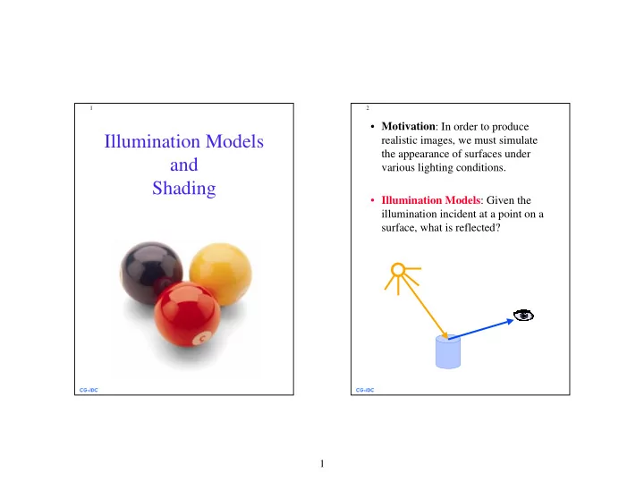
  • Motivation: In order to produce

realistic images, we must simulate the appearance of surfaces under various lighting conditions.

  • Illumination Models: Given the

illumination incident at a point on a surface, what is reflected?

slide-2
SLIDE 2

2

3

  • Illumination Model

Parameters

  • Lighting effects are described with

models that consider the interaction of light sources with object surfaces.

  • The factors determining the lighting

effects are: – The light source parameters:

  • Positions.
  • Electromagnetic Spectrum.
  • Shape.

– The surface parameters

  • Position.
  • Reflectance properties.
  • Position of near by surfaces.

– The eye (camera) parameters

  • Position.
  • Sensor spectrum sensitivities.

4

  • From Illumination Models

to Rendering

  • Illumination models is used to calculate

the intensity of light that is reflected at a given point on a surface.

  • Rendering methods use the intensity

calculations from the illumination model to determine the light intensity at all pixels in the image. – Considers light propagation between surfaces in the scene.

slide-3
SLIDE 3

3

5

  • Light Source Models
  • Point Source (A): All light rays originate

at a point and radially diverging.

– A reasonable approximation for sources whose dimensions are small compared to the

  • bject size.
  • Parallel source (B): Light rays are all
  • parallel. May be modeled as a point

source at infinity (the sun).

  • Distributed source (C): All light rays
  • riginate at a finite area in space.

– A nearby sources such as fluorescent light. A B C

6

  • Illumination Models
  • Simplified and fast methods for

calculating surfaces intensities.

  • Calculations are based on optical

properties of surfaces and the lighting conditions (no reflected sources nor shadows).

  • Light sources are considered to be

point sources.

  • A reasonably good approximation

for most scenes.

slide-4
SLIDE 4

4

7

  • Ambient Light
  • Assume there is some non-directional

light in the environment (background light).

  • The amount of ambient light incident
  • n each object is a constant for all

surfaces and over all directions.

  • The reflected intensity Iamb of any

point on the surface is: Ia - the ambient light intensity. Ka ∈ [0,1] - the surface ambient reflectivity.

  • In principle Ia and Ka are functions of

color, so we have IRamb, IGamb, IBamb

Iamb=Ka Ia

8

  • Examples: Ambient light reflections
slide-5
SLIDE 5

5

9

  • Diffuse Reflection
  • Diffuse (Lambertian) surfaces are

rough or grainy (like clay, soil, fabric).

  • The surface appears equally bright

from all viewing directions.

  • The brightness at each point is

proportional to cos(θ):

θ N L

10

  • This is because a surface (A)

perpendicular to the light direction is more illuminated than a surface (B) at an oblique angle.

  • The reflected intensity Idiff of any

point on the surface is: Ip - the point light intensity. May appear as attenuated source fatt(r)IP Kd ∈ [0,1] - the surface diffuse reflectivity. N - the surface normal. L - the light direction. A B

Idiff=Kd Ipcos(θ)=Kd Ip(N⋅L)

slide-6
SLIDE 6

6

11

  • Diffuse reflections from different

light directions

12

  • Ambient

surface Diffuse surface

slide-7
SLIDE 7

7

13

  • Commonly, there are two types of

light sources: – A background ambient light. – A point light source.

  • The updated illumination equation is

this case is:

  • Note this is the model for one color

and it should be duplicated for each channel: IR, IG, IB .

I=Idiff+Iamb=Kd Ip N⋅L + Ka Ia

14

  • 0.2

0.5 1.0 0.2 0.5 1.0

Ka Kd

slide-8
SLIDE 8

8

15

  • Specular Reflection
  • Shiny and glossy surfaces (like metal,

plastic) with highlights.

  • Reflectance intensity changes with

reflected angle.

  • For an ideal specular surface (mirror)

the light is reflected in only one direction - R.

  • However, most objects are not ideal

mirrors (glossy objects) and they reflect in the immediate vicinity of R.

θ θ N L R θ θ N L R φ V Ideal specular surface non-ideal specular surface

16

  • The Phong Model:

Reflected specular intensity falls off as some power of cos (φ): Ks - the surface specular reflectivity. n - specular-reflection parameter, determining the deviation from ideal specular surface (for mirror n=∞).

N N L L R R

Ispec=Ks Ipcosn(φ)=Ks Ip(R⋅V)n

V V φ φ Shiny surface Large n Dull surface Small n

slide-9
SLIDE 9

9

17

  • 2
  • 1.5
  • 1
  • 0.5

0.5 1 1.5 2 0.2 0.4 0.6 0.8 1

n=1 n=8 n=64

Plots of cosn(φ) for several specular parameter n.

18

  • The updated illumination equation

combined with diffuse reflection is:

  • If several light sources are placed in

the scene:

I= Iamb+Idiff+Ispec= Ka Ia+ Ip (Kd N⋅L+Ks (R⋅V)n) I= Iamb+Σk (Ik

diff+Ik spec)

slide-10
SLIDE 10

10

19

  • 0.2

0.5 1.0 0.2 0.5 1.0

Kd Ks

20

  • n=50

n=10 n=3

Several reflections with different specular parameters

slide-11
SLIDE 11

11

21

  • Diffuse

surface With additional specular component

22

  • Polygon Rendering

Methods

  • Given a freeform surface, one usually

approximates the surface as a polyhedra.

  • How do we calculate in practice the

illumination at each point on the surface?

  • Applying the illumination model at

each surface point is computationally expensive.

slide-12
SLIDE 12

12

23

  • Flat Shading
  • A single intensity is calculated for each

surface polygon.

  • A fast and simple method.
  • Gives reasonable result only if all of the

following assumptions are valid:

– The object is really a polyhedron. – Light source is far away from the surface so that N•L is constant over each polygon. – Viewing position is far away from the surface so that V•R is constant over each polygon.

24

  • Gouraud Shading
  • Renders the polygon surface by

linearly interpolating intensity values across the surface. The algorithm:

  • 1. Determine the average unit normal

at each polygon vertex.

  • 2. Apply an illumination model to

each vertex to calculate the vertex intensity.

  • 3. Linearly interpolate the vertex

intensities over the surface polygon.

slide-13
SLIDE 13

13

25

=

k k k k V

N N N

Step no 1

The normal Nv of a vertex is an average

  • f all neighboring normals:

26

  • I1

I2 I3 I4 I5

scan line

Step no 3

y x

2 2 1 4 1 1 2 1 2 4 4

I y y y y I y y y y I − − + − − =

3 2 3 5 3 2 2 3 2 5 5

I y y y y I y y y y I − − + − − =

IP

5 4 5 4 p 4 4 5 p 5 p

I x x x x I x x x x I − − + − − =

slide-14
SLIDE 14

14

27

  • Gouraud Shading of a sphere

28

  • Phong Shading
  • A more accurate method is for

rendering a polygon surface is to interpolate normal vectors, and then apply the illumination model to each surface point. The algorithm:

  • 1. Determine the average unit normal at

each polygon vertex.

  • 2. Linearly interpolate the vertex

normals over the surface polygon.

  • 3. Apply the illumination model along

each scan line to calculate pixel intensities for each surface point.

slide-15
SLIDE 15

15

29

  • Phong Shading of a sphere

30

  • Flat

Gouraud Phong

slide-16
SLIDE 16

16

31

  • Flat Shading

Gouraud Shading Phong Shading