
SLIDE 1
1
Illumination and Shading
In order to produce realistic images, we must
simulate the appearance of surfaces under various lighting conditions.
Illumination models: given the illumination incident
at a point on a surface, what is reflected?
Shading algorithms: determine when and how to
apply the illumination model, in order to provide a color for every visible surface point.
2
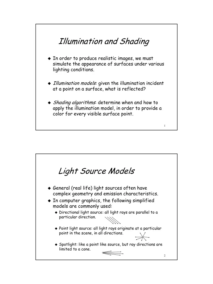
Light Source Models
General (real life) light sources often have
complex geometry and emission characteristics.
In computer graphics, the following simplified
models are commonly used:
Directional light source: all light rays are parallel to a
particular direction.
Point light source: all light rays originate at a particular
point in the scene, in all directions.
Spotlight: like a point like source, but ray directions are
limited to a cone.