I total = k s I ambient + I i ( i = 1 7 8 Lighting in OpenGL - - PDF document

i total k s i ambient i i i 1 7 8 lighting in opengl
SMART_READER_LITE
LIVE PREVIEW

I total = k s I ambient + I i ( i = 1 7 8 Lighting in OpenGL - - PDF document

University of British Columbia News: Homework CPSC 314 Computer Graphics homework correction: questions 13-16 should Jan-Apr 2005 use: Tamara Munzner unit square has points A=(0,0,0,1), B=(0,1,0,1), C=(0,1,1,1), D=(0,0,1,1) in world


slide-1
SLIDE 1

University of British Columbia CPSC 314 Computer Graphics Jan-Apr 2005 Tamara Munzner http://www.ugrad.cs.ubc.ca/~cs314/Vjan2005

Lighting and Shading Week 5, Wed Feb 2

2

News: Homework

homework correction: questions 13-16 should

use:

unit square has points A=(0,0,0,1),

B=(0,1,0,1), C=(0,1,1,1), D=(0,0,1,1) in world coordinates

homework clarification: question 1

C_i is down one-half unit and sideways one

unit.

3

News: Project Handin

when handing after the deadline, handin has this

unfriendly warning message

Checking that handin was successful ...

/cs/csbox/user FAILED to find user a1b2. Your files DO NOT appear to be handed in successfully

Do you want to cancel?

don’t panic

go ahead and complete the handin, do not cancel! your submission will be put in the LATE directory 4

Review: Reflectance

specular: perfect mirror with no scattering gloss: mixed, partial specularity diffuse: all directions with equal energy

+ + =

specular + glossy + diffuse = reflectance distribution

5

Review: Reflection Equations

Idiffuse = kd Ilight (n • l)

n l

  • 2 ( N (N · L)) – L = R

Ispecular = ksIlight(v•r)nshiny

6

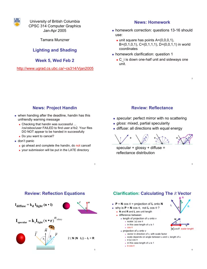
Clarification: Calculating The R Vector

P = N cos = projection of L onto N why is P = N cos , not L cos ?

N and R and L are unit length difference between length of projection of u onto v

scalar: |u| cos in this case length of u is 1 cos projection of u onto v vector in direction of v, with scale factor scale depends on angle between u and v, length of u v |u| cos in this case length of u is 1 v cos

L P N

  • u

v

  • cos

u

R

scalar length!

slide-2
SLIDE 2

7

Review: Reflection Equations 2

Blinn improvement full Phong lighting model

combine ambient, diffuse, specular components

l l n n v v h h

Itotal = ksIambient + Ii(

i=1 #lights

  • kd(n•li) + ks(v•ri)nshiny )

Ispecular = ksIlight(h•n)nshiny h = (l + v)/2

8

Review: Lighting

lighting models

ambient

normals don’t matter

Lambert/diffuse

angle between surface normal and light

Phong/specular

surface normal, light, and viewpoint 9

Lighting in OpenGL

light source: amount of RGB light emitted

value represents percentage of full intensity

e.g., (1.0,0.5,0.5)

every light source emits ambient, diffuse, and specular

light

materials: amount of RGB light reflected

value represents percentage reflected

e.g., (0.0,1.0,0.5)

interaction: multiply components

red light (1,0,0) x green surface (0,1,0) = black (0,0,0) 10

Lighting in OpenGL

!"#$!%&'()*#+#,*-./01*#+234,56.01789+"$!%&+:!971;< !"#$!%&'()*#+#,*-./01*#+=,>>?@501A$'+"$!%&+:!971;< !"#$!%&'()*#+#,*-./01*#+@B5C?#2D01EFGH+"$!%&+:!971;< !"#$!%&'()*#+#,*-./01*#+BI@,.,I601FJE$&$JK;< !"5K79"G)*#+#,*-./;< !"37&G:$7"'()1*#+>DI6.01*#+234,56.01789$GK&+:!971;< !"37&G:$7"'()1*#+>DI6.01*#+=,>>?@501A$''LEG+:!971;< !"37&G:$7"'()1*#+>DI6.01*#+@B5C?#2D01EFGHL"7:+:!971;< !"37&G:$7"'()1*#+>DI6.01*#+@-,6,65@@01K1;< warning: glMaterial is expensive and tricky

use cheap and simple glColor when possible see OpenGL Pitfall #14 from Kilgard’s list

http://www.opengl.org/resources/features/KilgardTechniques/oglpitfall/

11

Lighting vs. Shading

lighting

process of computing the luminous intensity

(i.e., outgoing light) at a particular 3-D point, usually on a surface

shading

the process of assigning colors to pixels (why the distinction?)

12

Applying Illumination

we now have an illumination model for a point

  • n a surface

if surface defined as mesh of polygonal facets,

which points should we use?

fairly expensive calculation several possible answers, each with different

implications for visual quality of result

slide-3
SLIDE 3

13

Applying Illumination

polygonal/triangular models

each facet has a constant surface normal if light is directional, diffuse reflectance is

constant across the facet.

why?

14

Flat Shading

simplest approach calculates illumination at a

single point for each polygon

  • bviously inaccurate for smooth surfaces

15

Flat Shading Approximations

if an object really is faceted,

is this accurate?

no!

for point sources, the

direction to light varies across the facet

for specular reflectance,

direction to eye varies across the facet

16

Improving Flat Shading

what if evaluate Phong lighting model at each pixel

  • f the polygon?

better, but result still clearly faceted

for smoother-looking surfaces

we introduce vertex normals at each vertex

usually different from facet normal used only for shading think of as a better approximation of the real surface

that the polygons approximate

17

Vertex Normals

vertex normals may be

provided with the model computed from first principles approximated by

averaging the normals

  • f the facets that

share the vertex

18

Gouraud Shading

most common approach, and what OpenGL does

perform Phong lighting at the vertices linearly interpolate the resulting colors over faces

along edges along scanlines

C1 C2 C3 edge: mix of c1, c2 edge: mix of c1, c3 interior: mix of c1, c2, c3

does this eliminate the facets?

slide-4
SLIDE 4

19

Gouraud Shading Artifacts

  • ften appears dull, chalky

lacks accurate specular component

if included, will be averaged over entire

polygon

C1 C2 C3 this interior shading missed! C1 C2 C3 this vertex shading spread

  • ver too much area

20

Gouraud Shading Artifacts

Mach bands

eye enhances discontinuity in first derivative very disturbing, especially for highlights

21

Gouraud Shading Artifacts

C1 C2 C3 C4 Discontinuity in rate

  • f color change
  • ccurs here

Mach bands

22

Gouraud Shading Artifacts

perspective transformations

affine combinations only invariant under affine,

not under perspective transformations

thus, perspective projection alters the linear

interpolation!

Z – into the scene Image plane

23

Gouraud Shading Artifacts

perspective transformation problem

colors slightly “swim” on the surface as objects

move relative to the camera

usually ignored since often only small difference

usually smaller than changes from lighting

variations

to do it right

either shading in object space

  • r correction for perspective foreshortening

expensive – thus hardly ever done for colors 24

Phong Shading

linearly interpolating surface normal across the

facet, applying Phong lighting model at every pixel

same input as Gouraud shading pro: much smoother results con: considerably more expensive

not the same as Phong lighting

common confusion Phong lighting: empirical model to calculate

illumination at a point on a surface

slide-5
SLIDE 5

25

Phong Shading

linearly interpolate the vertex normals

compute lighting equations at each pixel can use specular component

N1 N2 N3 N4

Itotal = kaIambient + Ii kd n li

( ) + ks v ri ( )

nshiny

( )

i=1 #lights

  • remember: normals used in

diffuse and specular terms discontinuity in normal’s rate of change harder to detect

26

Phong Shading Difficulties

computationally expensive

per-pixel vector normalization and lighting

computation!

floating point operations required

lighting after perspective projection

messes up the angles between vectors have to keep eye-space vectors around

no direct support in hardware

but can be simulated with texture mapping

27

Gouraud Phong

Shading Artifacts: Silhouettes

polygonal silhouettes remain

28

A D C B

Interpolate between AB and AD

  • B

A D C

Interpolate between CD and AD

Rotate -90o and color same point

Shading Artifacts: Orientation

interpolation dependent on polygon orientation

  • view dependence!

29

B A C vertex B shared by two rectangles

  • n the right, but not by the one on

the left E D F H G first portion of the scanline is interpolated between DE and AC second portion of the scanline is interpolated between BC and GH a large discontinuity could arise

Shading Artifacts: Shared Vertices

30

Shading Models Summary

flat shading

compute Phong lighting once for entire

polygon

Gouraud shading

compute Phong lighting at the vertices and

interpolate lighting values across polygon

Phong shading

compute averaged vertex normals interpolate normals across polygon and

perform Phong lighting across polygon

slide-6
SLIDE 6

31

Shutterbug: Flat Shading

32

Shutterbug: Gouraud Shading

33

Shutterbug: Phong Shading

34

Non-Photorealistic Shading

draw silhouettes: if , e=edge-eye vector cool-to-warm shading:

(e n0)(e n1) 0 http://www.cs.utah.edu/~gooch/SIG98/paper/drawing.html kw = 1+ n l 2 ,c = kwcw + (1 kw)cc