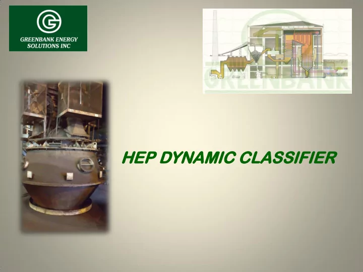

HE HEP D P DYN YNAM AMIC IC CL CLAS ASSI SIFIE FIER
Cl Classif assifica ication tion – Im Impa pact ct on Co Comb mbustion ustion Pulverized Coal Particle Size 1. The particle size distribution of the PF will affect the combustion taking place in the boiler 2. The larger a particle, the lower its surface area: volume ratio 3. Low NOx coal burners designed for 200 mesh (75 micron) particle size 4. The further from the 200 mesh ideal particle size the worse the impact on the combustion 5. The surface area to volume ratio affects how the particle will combust – primarily, how it will burn 6. Particles that are too large/coarse have an insufficient surface area to combust fully, as well as being physically excessively heavy, and will drop into the ash at the bottom of the furnace 7. Particles that are too small/fine have an excessive surface area and will combust too rapidly, increasing the flame temperature and catalyzing the formation of increased levels of NOx
Classification – Impact on Combustion NOx IDEAL LOI 45µm 75µm 220µm 325 mesh 200 mesh 65 mesh
Cl Classif assifica ication tion – Im Impa pact ct on Co Comb mbustion ustion Pulverised Coal Particle Size Distribution Variance 1. The slope of the graph is broadly analogous to the variance of the distribution 2. The Rosin Rammler slope gets steeper as the distribution of particle size gets narrower 3. Thus the goal of any classifier design is to minimize/eliminate all particles greater than 65 mesh and less than 325 mesh without increasing mill pressure drop 75µm 75µm
Clas assif sifier ier Typ ypes es Traditional Static Base Capacity @ slope 45º High Performance Static 2.5% Capacity = 1.25% on 75 micron @ slope 47º 1st / 2nd Generation Dynamic 5.0% Capacity = 2.50% on 75 micron @ slope 49º 4th Generation Dynamic 15.0% Capacity = 7.50% on 75 micron @ slope 5 2⁰
Brief rief Hi History tory of the e HE HEP The Fuller Co. was founded based on the development of the Kinyon Pump in 1919. The pump provided a safer way to transport pulverized coal to a boiler in a dilute phase pneumatic system and Fuller Co. became a leader in the development of transport and material classification for the coal and cement industry. In 1983 Fuller began supplying O-Sepa Dynamic Classifers for coal and cement. In 1990 the Fuller Co was purchased by FL Smidth of Denmark and had already begun development and sales of the HEP Dynamic Classifier for coal mills with over 350 units installed worldwide In 1992 Steel and Alloy Utility Products began manufacturing the HEP for Fuller / FLSmidth HEP Dynamic Classifiers sold in the US In 2016 Greenbank Energy and S&A have begun a joint venture to continue the manufacturing and sales of the product line.
HEP Classifier Operating Principle Fa = Aerodynamic Force As rotor speed increases, Fc = Centrifugal Force Fc increases As particle size increases. Fa decreases When: Fc - Fa ≥ 0 Particle is rejected Fc - Fa < 0 Particle is passed through
HEP Classifier Design Features Motor and Drive Belts Sealed Drive Bearing Externally Housing w/ Access Adjustable Guide Doors Vanes Rotor Cage Externally Adjustable Louvers Inlet Pre-Swirl Rejects Cone Vanes
HEP Classifier Design Features
HEP Classifier Design Features Designed specifically for each pulverizer and burner configuration Wear resistant materials used for extended wear life Sealed bearing and belt drive system Side mount rotor drive motor for low profile Externally adjustable louvers and guide vanes for online balancing Air/Fuel Ratio adjustable for pipe-to- pipe balance and improved combustion
Improved Air/Fuel Distribution To maximize the efficiency of low NOx burners, balanced air/fuel ratios must be delivered burner to burner Externally adjustable Guide Vanes at the coal pipe outlet can be set to maintain a 7% or better pipe to pipe balance of PF flow. This insures proper burner function as well as secondary and overfire air utilization to aid in NOx reduction
Questions? estions?
Recommend
More recommend