
SLIDE 1
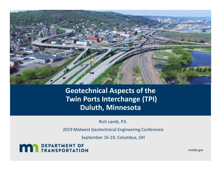
Geotechnical Aspects of the Twin Ports Interchange (TPI) Duluth, Minnesota
Rich Lamb, P.E. 2019 Midwest Geotechnical Engineering Conference September 16-19, Columbus, OH
mndot.gov
Geotechnical Aspects of the Twin Ports Interchange (TPI) Duluth, - - PowerPoint PPT Presentation
Geotechnical Aspects of the Twin Ports Interchange (TPI) Duluth, Minnesota Rich Lamb, P.E. 2019 Midwest Geotechnical Engineering Conference September 16-19, Columbus, OH mndot.gov Sorry, Wisconsin Project Location Duluth, Minnesota 2
Rich Lamb, P.E. 2019 Midwest Geotechnical Engineering Conference September 16-19, Columbus, OH
mndot.gov
4
5
6
7
8
9
10
11
12
13
mndot.gov/
15
16
9/24/2019 mndot.gov 17
Very Dense Sand >150 ft. Bedrock Dense Sand Org Silty Clay Sand fill Bedrock
Vert Dense Sand/Silt
Clay
Stiff Silt and Clay
Sand fill Dense Sand
Clay
9/24/2019 mndot.gov 18
9/24/2019 mndot.gov 19
9/24/2019 mndot.gov 20
21
22
23
24
25
26
27
28 9/24/2019 mndot.gov 28
29 9/24/2019 mndot.gov 29
30
9/24/2019 mndot.gov 31
9/24/2019 mndot.gov 32
33
9/24/2019 mndot.gov 34
9/24/2019 mndot.gov 35
9/24/2019 mndot.gov 36
37
38
39
9/24/2019 mndot.gov 40
41
42
43
44
45
46
47
9/24/2019 mndot.gov 48
49
9/24/2019 mndot.gov 50
(70-95% of embankment load)
9/24/2019 mndot.gov 51
52
9/24/2019 mndot.gov 53
Exit 535 EB
54
9/24/2019 mndot.gov 55
9/24/2019 mndot.gov 56
9/24/2019 mndot.gov 57
9/24/2019 mndot.gov 58
9/24/2019 mndot.gov 59
9/24/2019 mndot.gov 60
mndot.gov/
9/24/2019 mndot.gov 63
64
65
66
67 9/24/2019 mndot.gov 67
68 9/24/2019 mndot.gov 68
69
70
71
72
73
74
75
76
77