
SLIDE 1
1
Combinational Logic
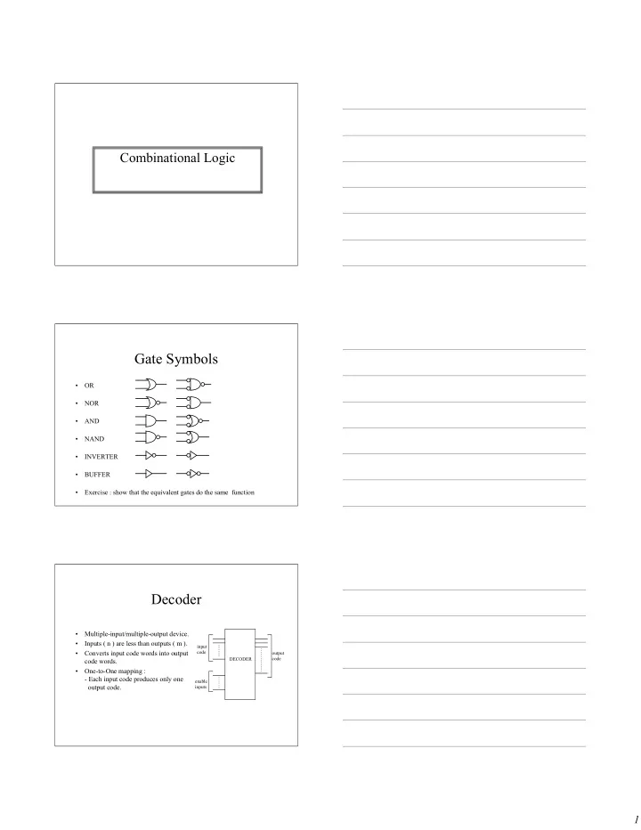
Gate Symbols
- OR
- NOR
- AND
- NAND
- INVERTER
- BUFFER
- Exercise : show that the equivalent gates do the same function
Decoder
- Multiple-input/multiple-output device.
- Inputs ( n ) are less than outputs ( m ).
- Converts input code words into output
code words.
- One-to-One mapping :
- Each input code produces only one
- utput code.
input code enable inputs
- utput
code DECODER