fusion relevant neutron source by Juan Knaster* on behalf of - - PowerPoint PPT Presentation

fusion relevant neutron source by juan knaster on behalf
SMART_READER_LITE
LIVE PREVIEW

fusion relevant neutron source by Juan Knaster* on behalf of - - PowerPoint PPT Presentation

FNS/1-2Ra & MPT/1-Rb (1) The accomplishment of the engineering design activities of IFMIF/EVEDA: The European-Japanese project towards a Li(d,xn) fusion relevant neutron source by Juan Knaster* on behalf of IFMIF/EVEDA family (2)


slide-1
SLIDE 1

1

(1) The accomplishment of the engineering design activities of IFMIF/EVEDA: The European-Japanese project towards a Li(d,xn) fusion relevant neutron source by Juan Knaster* on behalf of IFMIF/EVEDA family *Absent in FEC 2014

due to unsurmountable difficulties in obtaining the VISA

(2) Evaluation of Li Target Facility of IFMIF in the IFMIF/EVEDA Project by Eiichi Wkai (JAEA) on behalf of IFMIF/EVEDA family

FNS/1-2Ra & MPT/1-Rb

slide-2
SLIDE 2

2

  • J. Knaster

FEC 2014 – Saint Petersburg

IFMIF: International Fusion Materials Irradiation Facility EVEDA: Engineering Validation & Engineering Design Activities Article 1.1 of Annex A of the BA Agreement mandates IFMIF/EVEDA …to produce an integrated engineering design of IFMIF and the data necessary for future decisions on the construction, operation, exploitation and decommissioning of IFMIF, and to validate continuous and stable operation of each IFMIF subsystem ( Signed in February 2007, Entered into force on June 2007)

IFMIF/EVEDA

slide-3
SLIDE 3

3

  • J. Knaster

FEC 2014 – Saint Petersburg

IFMIF evaluation has successfully passed through all needed key steps as below:  Conceptual Design Activity (CDA) phase in 1996 As a joint effort of the EU, Japan, RF and US  Conceptual Design Evaluation (CDE) report in 1998 Towards a design simplification and cost reduction  The Conceptual Design Report (CDR) in 2004 Co-written by a committee of EU, Japan, RF, US  The final Phase of EVEDA within BA activities from 2007 As an efficient risk mitigation exercise to face the construction on cost and schedule timely with the world needs for a fusion relevant neutron source

IFMIF through all technical steps

slide-4
SLIDE 4

4

  • J. Knaster

FEC 2014 – Saint Petersburg

IFMIF Concept

Availability of facility >70%

A flux of neutrons of ~1018 m-2s-1 is generated in the forward direction with a broad peak at 14 MeV

125 mA CW deuterons at 40 MeV collide on a liquid Li screen flowing at 15 m/s

and irradiate three regions >20 dpa/y in 0.5 liters >1 dpa/y in 6 liters <1 dpa/y in 8 liters Materials will be tested in the PIE

slide-5
SLIDE 5

5

  • J. Knaster

FEC 2014 – Saint Petersburg

A Fruitful International Collaboration

IFMIF/EVEDA A fruitful Japanese- European International collaboration under the BA Agreement with 7 countries involved with the respective main research labs in Europe and main universities in Japan

slide-6
SLIDE 6

6

  • J. Knaster

FEC 2014 – Saint Petersburg

EVEDA Phase presents two parallel work packages EDA Phase Engineering Design Activities EVA Phase Engineering Validation Activities

Two Work Packages

slide-7
SLIDE 7

7

  • J. Knaster

FEC 2014 – Saint Petersburg

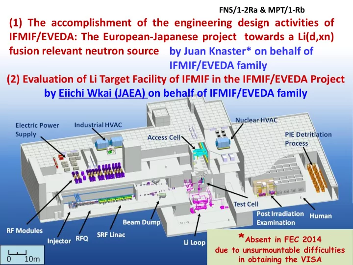
The Design of IFMIF is broken down to 5 facilities

Accelerator Facility Lithium Target Facility Test Facility Post-irradiation and Examination Facility Conventional Facilities

Lithium Target Thickness 25±1 mm Flow speed 15 m/s

Test Cell

Li Dump tank EMP Dump Tank Ti Trap Cold trap Y Trap

Impurity control system

Cooling water from /to Conventional Facilities EMP Quench tank Pump Secondary Heat Exchanger Dump Tank Pump Tertiary Heat Exchanger

Heat removal system

Primary Heat Exchanger

Secondary

  • il loop

Tertiary oil loop Main Li loop RFQ Ion source LEBT MEBT HEBT Superconducting cavities

1 k e V 5 M e V 9 1 4 . 5 2 6 4 M e V

Access Cell

Test Modules Handling cells Test Facility Ancillary systems

Test Facility

Be Hot Cell Lab. Tritium Hot Cell Lab. Liquid Metal Lab. Macrography Lab. Microscopy Lab. Hot Cell Laboratory

Post Irradiation Examination Facility

100 keV 5 MeV 9 14.5 26 40 MeV

RFQ Ion source Superconducting cavities LEBT M E B T

Accelerator Facility

PIEF Ancillary systems Maintenance systems RH systems Test Modules

Target system

Lithium Target Facility Conventional Facility

Buildings Site General Infrastructures Plant Services

AF Ancillary systems LF Maintenance systems LF Ancillary systems

EMFM Lithium Target Thickness 25±1 mm Flow speed 15 m/s

Test Cell

Li Dump tank EMP Dump Tank Ti Trap Cold trap Y Trap

Impurity control system

Cooling water from /to Conventional Facilities EMP Quench tank Pump Secondary Heat Exchanger Dump Tank Pump Tertiary Heat Exchanger

Heat removal system

Primary Heat Exchanger

Secondary

  • il loop

Tertiary oil loop Main Li loop RFQ Ion source LEBT MEBT HEBT Superconducting cavities

1 k e V 5 M e V 9 1 4 . 5 2 6 4 M e V

RFQ Ion source LEBT MEBT HEBT Superconducting cavities

1 k e V 5 M e V 9 1 4 . 5 2 6 4 M e V

RFQ Ion source LEBT MEBT HEBT Superconducting cavities

1 k e V 5 M e V 9 1 4 . 5 2 6 4 M e V

Access Cell

Test Modules Handling cells Test Facility Ancillary systems

Test Facility

Be Hot Cell Lab. Tritium Hot Cell Lab. Liquid Metal Lab. Macrography Lab. Microscopy Lab. Hot Cell Laboratory

Post Irradiation Examination Facility

100 keV 5 MeV 9 14.5 26 40 MeV

RFQ Ion source Superconducting cavities

100 keV 5 MeV 9 14.5 26 40 MeV

RFQ Ion source Superconducting cavities

100 keV 5 MeV 9 14.5 26 40 MeV

RFQ Ion source Superconducting cavities LEBT M E B T

Accelerator Facility

PIEF Ancillary systems Maintenance systems RH systems RH systems Test Modules

Target system

Lithium Target Facility Conventional Facility

Buildings Site General Infrastructures Plant Services Buildings Site General Infrastructures Plant Services

AF Ancillary systems LF Maintenance systems LF Ancillary systems

EMFM

Objective of Validation activities

Design of IFMIF

slide-8
SLIDE 8

8

  • J. Knaster

FEC 2014 – Saint Petersburg

EVA Phase Advancing Successfully

  • J. Knaster et al., IFMIF: overview of the validation activities, Nuclear Fusion 53 (2013) 116001 (18 pp)
slide-9
SLIDE 9

9

  • J. Knaster

FEC 2014 – Saint Petersburg

Complete WBS, detailed 3D models of plant, RAMI of individual facilities, remote handling studies, DDDs of all sub-systems (x35), licensing scenarios, safety reports, cost and schedule…

EDA Phase Accomplished on Schedule

slide-10
SLIDE 10

10

  • J. Knaster

FEC 2014 – Saint Petersburg

Report available upon request at ifmif-eveda@ifmif.org

slide-11
SLIDE 11

11

  • J. Knaster

FEC 2014 – Saint Petersburg

 Alvarez-type Drift Tube Linac replaced by a Superconducting RF Linac Reduction in beam losses and operation costs  Configuration of the Test Cell changed irradiation modules have no more a shielding function Improved irradiation flexibility and the reliability of the remote handling equipment  Quench Tank of the Lithium loop re-located outside the Test Cell Reduction of tritium production rate and simplification of maintenance processes  Maintenance strategy modified Allowing a shorter yearly stop of the irradiation operations and a better management of the irradiated samples.

Mario Pérez and the IFMIF/EVEDA Integrated Project Team The Engineering Design Evolution of IFMIF: from CDR to EDA Phase SOFT 2014

Main Design Improvements from CDR

(CDR: Comprehensive Design Report)

slide-12
SLIDE 12

12

  • J. Knaster

FEC 2014 – Saint Petersburg

Risk Analysis

slide-13
SLIDE 13

13

  • J. Knaster

FEC 2014 – Saint Petersburg

Possible inquiries please juan.knaster@ifmif.org

  • r at

+81 (0) 175 71 66 35 www.ifmif.org Wikipedia

  • J. Knaster et al., IFMIF, a fusion relevant neutron

source for material irradiation current status, Journal of Nuclear Materials 453 (2014) 115–119

slide-14
SLIDE 14

14

  • J. Knaster

FEC 2014 – Saint Petersburg

Evaluation of Li Target Facility of IFMIF in the IFMIF/EVEDA Project

by Eiichi Wkai (JAEA) on behalf of IFMIF/EVEDA family

Part II:

EVEDA Li Test Loop constructed in JAEA-Oarai

slide-15
SLIDE 15
  • D+-Li stripping reaction generates high

intense neutrons to simulate fusion irradiation conditions.

  • High-speed liquid Li flow along concave

back plate is selected as IFMIF target to handle a high heat load of 10MW D+ beams.

IFMIF Liquid Lithium Target Concept

Liquid Li Condition:

  • Temp.: 250oC,
  • Velocity: 15 m/s
  • Vacuum: 10-2-10-3 Pa

15

slide-16
SLIDE 16
  • Validation of stable long-time operation of a high-speed

free-surface liquid Li simulating IFMIF target.

  • Validations of diagnostics on the Li flow and impurity

control systems for a Li loop.

Main Missions of EVEDA Li Test Loop (ELTL)

  • Averaged heat flux

: 1 GW/m2

  • Jet velocity

: 15 m/s (range 10-20 m/s)

  • Jet thickness/Width

: 0.025 m/0.26 m

  • Surface wave amplitude

: < +/- 1 mm

  • Initial (inlet) Li temperature: 250 oC
  • Vacuum pressure

: 10-3 - 10-2 Pa near Li free surface

Major Requirements for Li Target in IFMIF Main Missions of EVEDA Li Test Loop (ELTL)

16

slide-17
SLIDE 17

Engineering Design

Construction, operation and tests of EVEDA Li test loop(installed at Oarai) Erosion/Corrosion Diagnostics Li purification system

N H

Dump tank EMP

Nozzle

Li flow

Remote handling Li Safety handling

(the EU: Cavitation test, etc..)

(1) Functional tests of each equipment (2) Tests of high-speed fluid with a free surface under vacuum (3) Long-duration tests

・The tests for 1000 to 8000 hours in a small Li loop of the EU (F82H, Eurofer 97) ・Wave height measurement of high- speed Li flow ・Applicability evaluation of diagnostics by a Li loop at Osaka Univ. ・Assistance analysis by a water test loop ・Replacement of the integrated target assembly (Japan). ・Replacement of only the backplate (the EU).

Nozzle

Target assembly Cold trap (O, Be, etc.) Impurity monitors (H, N, O, C etc.) Impurity traps(N, T(D))

・Removal of impurities in Li, impurity monitors

Engineering Validation Research

・Li handling technology, fire extinguishing testing

Lithium Facility Subjects in IFMIF/EVEDA Projects

17

slide-18
SLIDE 18

Construction, operation and tests of EVEDA Li Test Loop (ELTL) – Schedule -

18

slide-19
SLIDE 19

Li Dump Tank Heat Exchanger of Air cooling type Air Duct of Heat Exchanger Confinement Vessel for Lithium flowing with free surface in target assembly First floor: EMP, Cold trap, Cavitation Sensor, etc. Second floor: Li sampler, Heat Exchanger, Cavitation

sensor Cabinet

Third floor: Target vessel, A part of Quench Tank, etc. Under ground level: Li dump tank. (2.5 ton Li (5000 L)

20 m in Height

Vacuum pump for Target Vacuum pump  This height was needed to prevent the occurrence of cavitation in Electro-Magnetic Pump.

World largest liquid Li test loop constructed by JAEA in Oarai-site ( Nov. 2010)

19

slide-20
SLIDE 20

20

MAIN MEASUREMENT APPARATUS (DIAGNOSTICS)

Instrument Model, Mfr Major spec.

Flow rate EMF(Electro- magnetic flow meter)

Sukegawa electric Co., Ltd. Range: 0 ~ 3000 L/min (operational range) Accuracy (2σ): +/-55.8 [L/min] or 1.86 % FS*

Pressure Pressure gauge PTU-S, Swagelok

Range: - 0.1 to 0.3 MPaG Accuracy: +/- 0.5 % FS

Cold- cathode Pirani gauge

M-360CP-SP/N25, Cannon Anelva Corp. Range: 5 x 10⁻⁷ to 1 x 10⁵ (Pa) Accuracy: +/- 30 % RD**

Target Flow Obser.& Meas. Video camera

HVR-Z7J, Sony Record format: HDV1080/60i

Digital still camera

D800 (Lens: AS Nikkor 28- 300 mm), Nikkon Number of pixels: 36.3 M

Laser Distance meter

Optical Comb Absolute Distance Meter ML-5201D1- HJ, Optical Comb, Inc. See: Next page

* FS: Full Scale, **RD: Reading The flow rate and pressure were recorded in a control PC in the central control room every one second. On the other hand, the appearance of the Li target was monitored and recorded by a video camera and a digital camera.

Table:. Model and major specifications of the instruments

20

slide-21
SLIDE 21

Item Value (IFMIF condition) Mean Li jet speed Um [m/s] 10, 15, 20 (10 ~ 16) Inlet Li temperature [°C] 250 (or 300) Vacuum pressure Pv [Pa] 1.6 ~ 4.0 x 10⁻³ (10-3 ~ 10-2 ) 1.6 ~ 2.1 Measurement positions [mm]* At Y = 0 mm: -50 <= X <= 50 At X = 0 mm: -50<= Y <= 50 (-25 <= X <= 25 and -20 <= Y <= 20) Whole measurement range:

  • 50 <= X <= 50 and -50 <= Y <= 50

(-25 <= X <= 25 and -20 <= Y <= 20) Sampling frequency [kHz] 500 Data recording time [sec] 60 (one-turnover circulation time of approximately 60 s at 15 m/s) Laser wavelength [nm] 1550 Laser spot diameter [mm] 0.13 (determined based on the preliminary result) Measurement error [mm] (Evaluated experimentally) 0.04 (for target thickness) 0.02 (for wave height)

*The intervals of measurement positions are 10 or 15 mm for the X direction and 5 mm for the Y direction.

Specification of Laser Distance Meter

21

slide-22
SLIDE 22

22

  • J. Knaster

FEC 2014 – Saint Petersburg

V = 15.1 m/s, P = 1.3 x 10⁻³ Pa T = 250 oC

Flow appearance of Li target

(a) Flow straightener (b) Double contraction nozzle (c) Target flow channel (back plate) (d) Viewing port

Nozzle Side wall Side wall 196.97 30 30 50 B/C 100

slide-23
SLIDE 23

23

  • J. Knaster

FEC 2014 – Saint Petersburg

15 m/s, 3 Pa, 250 oC

(X,Y)=(0,0): B/C Mean : 0.52 mm

  • Max. : 3.26 mm

15 m/s, 10-3 Pa, 250 oC

Average thickness :

  • 26.08 +/- 0.08 mm (1σ) at B/C
  • Nonuniformity (max.-min.) is 0.16 mm

Wave amplitude (= height/2):

  • Mean : 0.26 +/- 0.02 mm (1σ) at B/C
  • 99.7 % are less than 1 mm (requirement)
  • Weilbull Distribution

Wave height distribution

  • T. Kanemura, H. Kondo et al., “Measurement of Li-target thickness

in the EVEDA Li Test Loop”, To be published in Fus. Eng. Des.

12

Time-averaged thickness of Li flow

  • 3D image -
  • Laser-distance meter (Optical Comb Inc.)

Time-of-flight (TOF) measurement

  • Analysis method:

Zero-up crossing method for average thickness and statistical properties of wave height

Laser-probe method

B/C

Li target measurement

slide-24
SLIDE 24

24

  • J. Knaster

FEC 2014 – Saint Petersburg

Long-time stability of the Li target was successfully demonstrated.

Day 1 Day 25

  • Period: 1 month (2 – 26 Sep. 2014)
  • Condition: Li target (15 m/s, 300 – 250 oC,

120 kPa) in parallel with the purification system (cold trap at 200 oC)

 Stable Li target throughout the continuous operation  Accumulated time of Li target

  • peration > 1000 hours

(At present it is continuing the Li flowing up to end of Oct. 2014)

Our Target Area for Design Requirement

Long-time continuous operation

slide-25
SLIDE 25

1. The Li target in the IFMIF conditions (250 oC, 15 m/s, 10-3 Pa) and its stability were successfully demonstrated.

  • Average thickness: 26.08 ± 0.08 mm (1σ)
  • Mean wave amplitude: 0.26 ± 0.02 mm (1σ)
  • Maximum wave amplitude: 1.45 ± 0.14 mm (1σ)

The maximum wave amplitude is very few over the design requirement of 1 mm, and 99.7 % of the total wave components are within the requirement. Therefore, we confirmed that the Li target of the current design was quite stable and satisfies the design

  • requirement. We finally validated the Li target stability.
  • 2. Continuous long-term operation of the Li target was conducted

(continuous operation: 1 month, accumulated time: >1000 h).  Validation of the Li target was the highest priority subjects for the Li target system of the IFMIF/EVEDA project. To achieve this goal, we designed and constructed the ELTL, and produced a stable Li target that complies with IFMIF requirements.

(The validation operation of the Li test loop is continuing up to the end of Oct. 2014.)

Li Target Validation Tests - Summary -

25

slide-26
SLIDE 26

Thank you for your attention

26

slide-27
SLIDE 27

Items ELTL IFMIF Lithium Facility Nozzle design Double- contraction Double- contraction Back wall Concave (316L) Concave (RAFM) Jet thickness [mm] 25 mm 25 mm Jet width [mm] 100 mm 260 mm

  • Max. jet velocity / surface

pressure [m/s] 20/10-3 Pa to atmospheric pressure 15 (max.16)/ <10-2 Pa

  • Max. flow rate [L/s]

50 L/sec 133 L/sec Temperature [°С] 250-350℃ 250-300℃ Li inventory [m3] 5.0 m3 9 m3 Status In Operation Design stage

Specification of ELTL and IFMIF LF

27

slide-28
SLIDE 28

Erosion/corrosion

ENEA Brasimone Lithium Loop: Lifus 6

Material Exposure [h] F82H/ Eurofer ~ 1000 ~ 2500 ~ 3500

  • To perform corrosion/erosion tests at constant temperature (reference

350°C) and velocity (reference 16 m/s in test section) under the purification control for Li with less than 30 wppm N

  • To test lithium purification and impurities monitoring systems

including Purification

28

slide-29
SLIDE 29

(a)Flow Straightener

  • A honeycomb for removing

large scale turbulence.

  • Three perforated plates for

flattening velocity distribution.

(b) Contraction Nozzle

  • Two-step contraction,

contraction ratio is 10. (250 mm to 25 mm in thickness) To obtain flow velocity up to 20 m/s.

(c) Target Flow Section (back plate)

i) Flow Width and Thickness : 100 and 25 mm ii) Viewing Ports: Two Ports

29

Li inventory 2.5 tons (5000 l) Li flow rate 3000 L/min (max.) EM flow meter range  3000 L/min Li flow velocity in Target  20 m/s Material S.S. 304 for pipe, 316L for back- plate Li temp. 250-350 °C Design temp. 400 °C Design pressure 10-3 Pa to 0.75 MPa G

Design Specification of Proto Type of EVEDA Lithium test loop (ELTL)

29

slide-30
SLIDE 30

Measurement for Li free surface in ELTL (Non-Contact Method – Developed Laser distance meter )

  • Fig. Interference condition of laser

The present laser condition:

  • Spot diameter: 0.1 mm (MFD)
  • Laser incident angle: 0.85o

   

dx dy x A y / tan / 2 sin

1 

    

  • Fig. Slope angle α (solid line) with sine curve y (dashed

line)

The incident laser is returned to the laser head from the region of 0.044 mm. This means 62 % of the total energy is returned (the laser energy is distributed to normal distribution), which is considered to be large enough for a significant signal. A: 0.28 mm λ: 4 mm [3]

30

slide-31
SLIDE 31

31

Laser Head

Nozzel

Hatch for measurement PRECISION POSITIONING STAGE Base of Laser head

X Direction Li Flow

Optical bench

Target Assembly

Figure: Setting of measurement instruments

Y Direction Z direction Origin (X,Y)=(0,0)

Laser Distance Meter

slide-32
SLIDE 32

The solid red line denotes the Rayleigh distribution, The dashed blue line denote the Weibull distribution, the “parent” distribution of the Rayleigh distribution, Nondimensional wave height distribution at Pv = 10-3 Pa

(1) (2)

  • The target stability limit: 2 mm in wave height H
  • Mean wave height 𝐼

≈ 0.5 mm for all data

  • Thus, nodimensional stability limit: 𝐼/𝐼

≈ 4 99.7 % of the total wave components is within the limit!

where k > 0 is the shape parameter and λ > 0 is the scale parameter of the

  • distribution. When k = 2 and λ = 4/𝜌, Eq. (2) is reduced to Eq. (1). The

parameter of the fitting curve is k = 1.73 ± 0.03, λ = 1.07± 0.02.

𝑸 𝑰 = 𝝆 𝟑 𝑰 𝑰 𝒇𝒚𝒒 − 𝝆 𝟓 𝑰 𝑰

𝟑

𝑸 𝒀 = 𝒍 𝝁 𝒀 𝝁

𝒍−𝟐

𝒇𝒚𝒒 − 𝒀 𝝁

𝒍

Stability limit!

Temporal fluctuation

32

slide-33
SLIDE 33

Three-dimensional plot of the average thickness of the Li target at Um = 15 m/s at Pv = 1.8 Pa. (Black symbols denote measurement data)

Average thickness distribution along the Y (spanwise) direction at X = 0. Average thickness distribution along the X (streamwise) direction at Y = 0. The area corresponding to the IFMIF beam footprint (-25 <= X <= 25 and -20 <= Y <= 20) Un-uniformity inside the beam footprint was

  • 0.16 mm along the Y (spanwise) direction,
  • 0.10 mm along the X (streamwise) direction.

The Li target is adequately smooth on average. Beam center Flow direction Flow direction Sliced at Y = 0 Sliced at X = 0

Average thickness of Li Target

Presented by T. Kanemura in SOFT2014

33

slide-34
SLIDE 34

Statistics of measurement results

Um [m/s] 10 15 20 Design requirement N* 5 6 2

  • Amean

[mm]** 0.23 ± 0.02 (1σ) *** 0.26 ± 0.02 (1σ) *** 0.24 ± 0.01 (1σ) *** 1 mm Amax [mm]** 1.50 ± 0.11 (1σ) *** 1.45 ± 0.14 (1σ) *** 1.66 ± 0.10 (1σ) *** ηmean [mm] 25.73 ± 0.07 (1σ) *** 26.08 ± 0.08 (1σ) *** 26.15 ± 0.08 (1σ) *** 25 mm N: the number of the data samples, Amean: Mean wave amplitude, Amax: Maximum wave amplitude, ηmean : Average thickness *The data were obtained on different days to check reproducibility. **Amplitude A is half wave height (A = H/2). ***Measurement uncertainty includes variation of measured data itself and measurement error.

Statistics of measurement results obtained at the beam center (X, Y) = (0, 0) under the IFMIF condition.

The Li target of the current design is quite stable and satisfies the design requirement.

Presented by T. Kanemura in SOFT2014

34

slide-35
SLIDE 35

Purification of Lithium

1000/T ( K-1 ) Solubility ( at.ppm )

O C H N

Solubility of H, C, N, O in Li

1 10 10

4

10

5

1 1.2 1.4 1.6 1.8 2 2.2 10

2

10

3

Temperature ( ℃ )

200 300 400 500 600

Cold trap: 453~500K

Formation of Li-Cr-N is one of the most serious corrosion for S.S.

(>60~70wppmN)

YN is very stable, which degrades hydrogen gettering efficiency . ⇒Titanium react with N even N in Li is less than 1wppm C, O: solubility is small enough to use cold trap.

Purposes of impurity reduction

suppression of corrosion (C, N, O) suppression of erosion (H(?), C, O) reducing of radio-activity of Li (T(H,D)) preventing Y from degradation (N, O) N: Hydrogen distribution ratio between Y/Li is very large. However, Yttrium easily react with N and O in Li H:

Total content of H isotope in Li ( 10 wppm) T content in Li ( 1 wppm) N content in Li ( 10 wppm) O content in Li ( 10 wppm)

35