Expanded Conformal Array Sonar Atlas next generation of Bow and - - PDF document

expanded conformal array sonar atlas next generation of
SMART_READER_LITE
LIVE PREVIEW

Expanded Conformal Array Sonar Atlas next generation of Bow and - - PDF document

UDT 2020 UDT Extended Abstract Presentation/Panel Expanded Conformal Array Sonar Atlas next generation of Bow and Flank Array Sebastian Hess 1 1 M. Sc., Atlas Elektronik GmbH, Bremen, Germany Abstract The ATLAS Expanded Conformal Array


slide-1
SLIDE 1

UDT 2020 UDT Extended Abstract Presentation/Panel

Expanded Conformal Array Sonar – Atlas next generation of Bow and Flank Array

Sebastian Hess1

  • 1M. Sc., Atlas Elektronik GmbH, Bremen, Germany

Abstract — The ATLAS Expanded Conformal Array Sonar (ECAS) is a modular, passive bow array sonar for submarines. It is designed for detecting acoustic signals in the medium frequency band by virtue

  • f broadband, narrowband, and intercept signal processing. The modular design of the ECAS system is

characterized by discrete modules which can be easily adapted to any contour and arranged into various setups such as Bow Arrays, Aft Sector Arrays or Flank Arrays.

1 Introduction

Nowadays, the requirements for submarines are ever-

  • changing. Since every navy operates in different
  • perational areas and has different conops together with a

specific submarine design, it comes with very unique needs for detection capabilities, challenging contours and sonar features. This demands tailored solutions for the underwater systems resulting in high development and integration times and increasing cost. ECAS, the new bow array from ATLAS ELEKTRONIK, is an innovative design combining the need for individual platform requirements and the efficient accessibility of

  • ptimum sonar performance on all platforms.

The key features of ECAS are:

  • High levels of adaptability to different platform

contours or functionality

  • High sensitivity and detection performance
  • Cost-effective solution for increased number of

signal channels

  • Modular design (all electrical units are line-

replaceable)

  • Enhanced

Availability due to automated production line

2 System decomposition

The ECAS signal chain starts with an acoustic module, the Hydrophone Panel, which converts the acoustic signals to electric analogue signals over multiple individual channels. The electric signal is then processed and converted to digital signals in the Sensor Electronic (SE) and merged in the Junction Tube (JT). The JT transmits the data to the inboard unit Sensor Interface Box (SI-Box) which processes the data and yields an interface for arbitrary imaging interfaces. By this decomposition the ECAS is not bound to just one

  • application. It can be adapted for integration as Bow

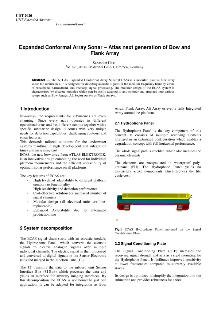
Array, Flank Array, Aft Array or even a fully Integrated Array around the platform. 2.1 Hydrophone Panel The Hydrophone Panel is the key component of this

  • concept. It consists of multiple receiving elements

arranged in an optimized configuration which enables a degradation concept with full horizontal performance. The whole signal path is shielded, which also includes the ceramic elements. The elements are encapsulated in waterproof poly- urethane (PU). The Hydrophone Panel yields no electrically active components which reduces the life cycle cost.

Fig.1 ECAS Hydrophone Panel mounted on the Signal Conditioning Plate

2.2 Signal Conditioning Plate The Signal Conditioning Plate (SCP) increases the receiving signal strength and acts as a rigid mounting for the Hydrophone Panel. It facilitates improved sensitivity at lower frequencies compared to currently available staves. Its design is optimized to simplify the integration into the submarine and provides robustness for shock.

slide-2
SLIDE 2

UDT 2020 UDT Extended Abstract Template Presentation/Panel 2.3 Sensor Electronic The Sensor Electronic is situated in pressure resistant housing located in the bow section. It can be placed independently from the Hydrophone Panel. The housing is made of corrosion resistant stainless steel and is tested to be shock proof. The simple design with integrated health monitoring makes it easy to replace any electrical part. The Sensor Electronic is designed to process up to 64 analogue channels. Its low power consumption design allows a single channel conversion – to? a large number

  • f channels. However, the SE brings additional system

fail safety by being able to process different groups of

  • ne Hydrophone Panel separately. Electrical self noise is

reduced beyond Sea State 0 by isolating the SE.

Fig.2 ECAS Sensor Electronic housing

2.4 Junction Tube The Junction Tube collects the data from up to six Sensor Electronics and streams it to the inboard Sensor Interface Box via optical 1000 Base-TX Ethernet. For system fail safety it features redundant power supply interface, synchronisation input and data transfer output.

Fig.3 ECAS Junction Tube

2.5 Sensor Interface Box The SI-Box is the inboard main interface for any signal processing and imaging components. It replaces the ATLAS Terminal Adapter (TAD) by merging the data stream capabilities and data processing. Its slim design and different interfaces facilitates easy inboard integration to arbitrary systems.

Fig.4 ECAS SI-Box

3 Design approach

ECAS is able to steer the vertical beams sophistically and can reduce the environmental noise which yields potential target separation and added detection range. The vertical beam steering serves also to compensate installation tilt angles and offers the additional advantage

  • f reducing noise influence from the sea

surface.Therefore data from every single hydrophone has to be transfered inboard individually as an enabling technology for vertical beam steering. The ECAS Hydrophone Panel yields enough single elements in one stave to fulfil modern needs of vertical beam steering without exceeding form factors or energy consumption. The design of underwater electronics is always a challenge and the latest technology iteration has become even more elaborate. To achieve optimum sonar performance, the number of hydrophones featured by these sonar antennas is crucial. It demands sonar antenna manufacturing at the highest standards by applying innovative automated production and quality control technologies. An automated manufacturing approach makes it possible to adapt to new applications easily while keeping the integration time low. By separating the SE from the Hydrophone Panel, the factor life cycle cost is taken into account. By making every unit line replaceable, a damaged Hydrophone Panel can be exchanged independently and spare parts come with reduced costs.

4 Conclusions

At the commencement of the ECAS design, the aim was to develop a system that is easy to adapt to any platform

  • contour. However, this has unravelled into a more

powerful system approach that yields many applications. With a set of standardized components with defined interfaces and a sensing element that is slim enough to fit in many positions but also performant enough to adapt to many applications it was possible to form more than just a Bow Array. ECAS in its early stage, is proven to be compatible to applications such as Flank Array and Aft Sector Array. Its COTS-character puts development and integration time for a new platform to a minimum.

slide-3
SLIDE 3

UDT 2020 UDT Extended Abstract Template Presentation/Panel With this proven concept, ECAS will be the one-fits-all solution for future submarines that combines the key requirements of today: maximum performance combined with short time availability and minimized life cycle costs.