Diamond Light Source a New Light for Science Richard P. Walker, - - PowerPoint PPT Presentation

diamond light source a new light for science
SMART_READER_LITE
LIVE PREVIEW

Diamond Light Source a New Light for Science Richard P. Walker, - - PowerPoint PPT Presentation

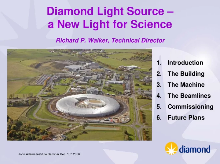
Diamond Light Source a New Light for Science Richard P. Walker, Technical Director 1. Introduction 2. The Building 3. The Machine 4. The Beamlines 5. Commissioning 6. Future Plans John Adams Institute Seminar Dec. 13 th 2006 What


slide-1
SLIDE 1

John Adams Institute Seminar Dec. 13th 2006

Diamond Light Source – a New Light for Science

Richard P. Walker, Technical Director 1. Introduction 2. The Building 3. The Machine 4. The Beamlines 5. Commissioning 6. Future Plans

slide-2
SLIDE 2

John Adams Institute Seminar Dec. 13th 2006

What is Synchrotron Light ?

  • Synchrotron Light is electromagnetic

radiation emitted when a high energy beam of charged particles (electrons) is deflected by a magnetic field

a single bending magnet produces a wide fan of radiation multiple bends in an "undulator" or "wiggler" magnet give higher intensity and brighter radiation

slide-3
SLIDE 3

John Adams Institute Seminar Dec. 13th 2006

What’s so special about it ?

  • Covers the

electromagnetic spectrum from microwaves to hard X-rays:

  • can select the wavelength

required for a given experiment synchrotron light

Wavelength (m)

visible light

  • Extremely intense and well collimated:
  • can be focused to sub-micron spot sizes, allows rapid

experiments on small and dilute samples

  • Highly polarised
  • generally linear, but circular also possible
  • Pulsed time structure
  • allows dynamic studies of fast chemical or biological processes

(10-100 ps scale)

slide-4
SLIDE 4

John Adams Institute Seminar Dec. 13th 2006

What can it be used for ?

Biomedical - protein crystallography and cell biology; Medical research - microbiology, disease mechanisms, high resolution imaging; Environmental science - toxicology, atmospheric research, clean combustion and cleaner industrial production technologies; Agriculture - plant genomics, soil studies and plant imaging; Advanced materials - nanostructured materials, intelligent polymers, ceramics, light metals and alloys, electronic and magnetic materials; Engineering - imaging of industrial processes in real time, high resolution imaging of cracks and defects in structures,

  • peration of catalysts in chemical engineering

processes; Forensic Science - identification from extremely small and dilute samples. Archaeometry - ancient metalworking processes, identification of production sites etc.

slide-5
SLIDE 5

John Adams Institute Seminar Dec. 13th 2006

A Brief History of Synchrotron Light Sources :

  • Discovery: 1947, General Electric 70 MeV synchrotron
  • First use for experiments: 1956, Cornell 300 MeV synchrotron
  • 1st generation:

machines built for other purposes, mainly High Energy Physics

e.g. Synchrotron Radiation Facility at the NINA Synchrotron, Daresbury (1971-1977)

  • 2nd generation:

purpose-built storage rings for synchrotron light

e.g. the SRS at Daresbury, the world's first dedicated synchrotron X-ray source (1981-2008)

  • 3rd generation:

higher brightness synchrotron light sources, using mainly undulators as the X-ray source

e.g. ESRF, Diamond etc.

slide-6
SLIDE 6

John Adams Institute Seminar Dec. 13th 2006

How does it work ?

A beam of electrons is accelerated in a linac, further accelerated in a booster, then accumulated in a storage ring. The circulating electrons emit intense beams of synchrotron light that are sent along beamlines to the experimental stations.

slide-7
SLIDE 7

John Adams Institute Seminar Dec. 13th 2006

Diamond Project Evolution

1993 Woolfson Review: SRS to be replaced by a new medium energy machine 1997 Feasibility Study (“Red Book”) published 3 GeV, 16 cells, 345 m circumference, 14 nm rads 1998 Wellcome Trust joins as partner

  • Mar. '00

Decision to build Diamond at Rutherford Appleton Lab.

  • Oct. '00

3 GeV, 24 cells, 560 m circumference design approved

  • Apr. '02

Joint Venture Agreement signed (UK Govt./WellcomeTrust) Diamond Light Source Ltd. established Design Specification Report (“Green Book”) completed by CCLRC

  • Jan. '07

Start of Operations

slide-8
SLIDE 8

John Adams Institute Seminar Dec. 13th 2006

Diamond Design Criteria

  • Large capacity for Insertion Device beamlines
  • High brightness synchrotron light from undulators optimised in

the range 0.1-10 keV, extending to 15-20 keV

  • High flux from wigglers up to 100 keV
  • Cost constraint
  • “medium” energy of 3 GeV
  • relatively large circumference (562 m) and no. of cells (24) to

give large no. of insertion devices and low emittance

  • extensive use of in-vacuum undulators
slide-9
SLIDE 9

John Adams Institute Seminar Dec. 13th 2006

it's all about brightness …

diamond

1.E+02 1.E+04 1.E+06 1.E+08 1.E+10 1.E+12 1.E+14 1.E+16 1.E+18 1.E+20

Brightness (Photons/sec/mm2/mrad2/0.1%) Candle X-ray tube 60W bulb X-rays from Diamond will be 1012 times brighter than from an X-ray tube, 105 times brighter than the SRS !

slide-10
SLIDE 10

John Adams Institute Seminar Dec. 13th 2006

Diamond – Main Parameters

Energy 3 GeV Circumference 561.6 m

  • No. cells

24 Symmetry 6 Straight sections 6 x 8m, 18 x 5m Insertion devices 4 x 8m, 18 x 5m Beam current 300 mA Emittance (h, v) 2.7, 0.03 nm rad Lifetime > 10 h

  • Min. ID gap

7 mm Beam size (h, v) 123, 6 µm Beam divergence (h, v) 24, 4 µrad

(at centre of 5 m ID) nominal, non-zero dispersion lattice

slide-11
SLIDE 11

John Adams Institute Seminar Dec. 13th 2006

Diamond is a one of a new class of Medium Energy, 3rd Generation Light Sources.

Comparison of 3rd Generation Synchrotrons

Diamond

Swiss Light Source APS (USA) PETRA III (Germany) ESRF Canadian Light Source SPring-8 (Japan) ELETTRA (Italy) Australian Synchrotron ALS (USA) SOLEIL (France) SPEAR3 (USA) BESSY II (Germany) MAX-II (Sweden) ALBA/CELLS (Spain) PLS (Korea)

2 4 6 8 10 12 14 16 18 20 1 2 3 4 5 6 7 8 9

Energy / GeV Emittance / nm rad

slide-12
SLIDE 12

John Adams Institute Seminar Dec. 13th 2006

Diamond compared to SRS

SRS Diamond Electron Beam Energy 2 GeV 3 GeV Storage ring circumference 96.0 m 561.6 m Available space for Insertion Devices 6x1m 4x8m, 18x5m Beam current 250 mA 300 mA Emittance (hor., vert.) (nm rad) 190, 3.8 2.7, 0.03 Minimum ID gap 20 mm 7 mm Electron beam sizes (hor., vert) (µm) 1000, 160 123, 6 Electron beam divergences (hor., vert) 590, 60 24, 4 µrad Peak brightness 3 1015 2 1020 Peak brightness (1Å) 1014 1019 100,000 times brighter than the SRS !

slide-13
SLIDE 13

John Adams Institute Seminar Dec. 13th 2006

Key Dates

  • Start enabling works
  • Mar. '03
  • Start main building works
  • Oct. '03
  • Linac commissioning
  • Aug. - Nov. '05
  • Booster commissioning
  • Jan. - Jun. '06
  • Storage ring commissioning

May – Dec. '06

Start of Operations

  • Jan. '07
slide-14
SLIDE 14

John Adams Institute Seminar Dec. 13th 2006

235 m

100 MeV Linac 3 GeV Booster

C = 158.4 m

3 GeV Storage Ring

C = 562.6 m

Experimental Hall and Beamlines

235 m

  • ffice

building peripheral

  • labs. and
  • ffices

future long beamlines

technical plant

Diamond Layout

slide-15
SLIDE 15

John Adams Institute Seminar Dec. 13th 2006

Diamond Buildings: architect’s concept to reality

“a spaceship landing in the natural landscape..” “the curved outer form reflects the form of the synchrotron within ..”

slide-16
SLIDE 16

John Adams Institute Seminar Dec. 13th 2006

piling rig:

Foundations designed to reduce ground movements and vibrations to the minimum practically achievable:

1523 piles, 12-15 m deep 600 mm diam., 3 m apart separate non- piled foundation for the building structure and plant rooms experimental hall storage ring tunnel 0.6-0.85 m thick concrete slab void to isolate slab from the ground

slide-17
SLIDE 17

John Adams Institute Seminar Dec. 13th 2006

Buildings and services also designed for thermal stability:

Courtesy of JacobsGibb Ltd. Local air handling unit Return air at labyrinth only Supply air duct with jet nozzle

  • utlets distributed

around ring Piped services distribution on wall at high level

experimental hall +/- 1 oC storage ring tunnel +/- 0.5 oC

slide-18
SLIDE 18

John Adams Institute Seminar Dec. 13th 2006

June 2003

slide-19
SLIDE 19

John Adams Institute Seminar Dec. 13th 2006

June 2004

slide-20
SLIDE 20

John Adams Institute Seminar Dec. 13th 2006

October 2005

slide-21
SLIDE 21

John Adams Institute Seminar Dec. 13th 2006

The Machine: Linac

  • 100 MeV Linac of the DESY S-band Linear Collider Type II design,

supplied "turn-key" by Accel Instruments. (DLS supplied diagnostics, vacuum and control system components, and beam analysis software)

  • thermionic gun; short (< 1 ns) and long pulse (0.1-1 µs) modes
  • 500 MHz sub-harmonic pre-buncher, 3 GHz primary buncher,

3 GHz final buncher

  • two 5.2 m constant gradient accelerating sections fed by

independent klystrons

slide-22
SLIDE 22

John Adams Institute Seminar Dec. 13th 2006

Booster

Energy 3 GeV Circumference 158.4 m Emittance 141 nm rad Repetition rate 5 Hz Lattice FODO, missing dipole

slide-23
SLIDE 23

John Adams Institute Seminar Dec. 13th 2006

Storage Ring

slide-24
SLIDE 24

John Adams Institute Seminar Dec. 13th 2006

Magnets and vacuum chambers

.. mounted and pre-aligned

  • n 72 precisely machined

girders. Up to 6 m long and 17 T in weight. mover system for remote alignment

slide-25
SLIDE 25

John Adams Institute Seminar Dec. 13th 2006

Power Supplies

Analog- Digital- Converter

Standardisation

  • minimum no. of different types
  • all 1038 power supplies use the

same (PSI type) digital controller and ADC cards. Maintainability and Reliability

  • plug-in modules
  • reduced component count
  • redundancy of 24 V control power

and power modules

DSP-controller

  • incl. PWM generator
slide-26
SLIDE 26

John Adams Institute Seminar Dec. 13th 2006

RF System

Supercon- ducting cavities (2) IOT-based 300 kW amplifiers Liquid He plant

slide-27
SLIDE 27

John Adams Institute Seminar Dec. 13th 2006

Resolution in 2 kHz Bandwidth: <1 µm at >10 mA Turn-by-turn (1 MHz b.w.): ~ 100 µm at 1 mA

10 10

1

10

2

10

  • 1

10 beam current [mA] resolution [um] mean maximum minimum production spec

  • riginal spec

10

  • 1

10 10

1

10

2

10 10

1

10

2

beam current [mA] beam current dependance [um] mean maximum production spec

  • riginal spec

Beam Current Dependence < 1 µm at 60-300 mA

Digital Beam Position Monitor Electronics

(Libera, integrated in EPICS)

slide-28
SLIDE 28

John Adams Institute Seminar Dec. 13th 2006

Phase I Insertion Devices

Beamline ID Type I02 U23 In-vacuum I06 HU64 APPLE-II I16 U27 In-vacuum I03 U21 In-vacuum U23 SCW U27 I04 In-vacuum I15 Superconducting Multipole Wiggler I18 In-vacuum

slide-29
SLIDE 29

John Adams Institute Seminar Dec. 13th 2006

Beamlines

  • Phase I: 7 beamlines –

ready for operations in January 2007

  • Phase II (funded):

15 additional beamlines at 4 per year from 2008 to 2011/12

  • Phase III (proposal):

10 additional beamlines, 2011-2015

slide-30
SLIDE 30

John Adams Institute Seminar Dec. 13th 2006

Scope of Research

  • Expected Usage

Engineering and Physical Sciences 48% Life Sciences 40% Environmental Sciences 12%

  • Reaching new communities from both academia & industry

Advanced techniques High throughput

slide-31
SLIDE 31

John Adams Institute Seminar Dec. 13th 2006

Beamline Plan – Science “Villages”

slide-32
SLIDE 32

John Adams Institute Seminar Dec. 13th 2006

Beamline Programme

Macromolecular Crystallography (U) Macromolecular Crystallography (U) Macromolecular Crystallography (U) Microfocus Spectroscopy (U) Nanoscience (U) Extreme Conditions (MPW) Materials and Magnetism (U)

2003 2004 2006 2005 2007 2008 2013 2009 2010 2011 2012

Non Crystalline Diffraction (U) Test Beamline (BM) Small Molecule Diffraction (U) High Resolution Powder Diffraction (U) Microfocus Macromolecular Crystallography (U) Circular Dichroism (BM) JEEP (MPW) Monochromatic MX Side Station (SS) Versatile X-ray Spectrometer (MPW) Surface & Interface X-ray Diffraction (U)

Beamlines in Operation

Phase I, in construction Phase II, in design / construction Phase II, confirmed 20 10

Core XAS (BM) IMS (BM) BLADE (HU) X-ray imaging (U) SISA (HU)

SRS closure

HATSAXS (BM) Long wavelength MX (U)

Phase III, to be approved

slide-33
SLIDE 33

John Adams Institute Seminar Dec. 13th 2006

Phase I Beamlines

  • I02,3,4

3-25 keV Macromolecular crystallography For the determination of the structure of macromolecules with rapid sample through-put.

  • I06

80- 1500 eV Nanoscience To study the morphology, chemical and magnetic state of nanostructures with <10 nm resolution.

  • I15

5-200 keV Extreme conditions Study of materials at very high temperatures and pressures, typical

  • f planetary interiors and industrial processes.
  • I16

3-25 keV Materials and magnetism Study of materials including magnetic systems, high temperature superconductors.

  • I18

2-13 keV X-ray microfocus spectroscopy Chemical imaging and structural studies of complex multicomponent systems with sub-micron resolution.

slide-34
SLIDE 34

John Adams Institute Seminar Dec. 13th 2006

User Access

  • User Office is operational
  • Call for first users: October 2006
  • First “experienced” users and optimisation of Phase I beam

lines: January - September 2007

  • Call for 2nd user proposals: May 2007
slide-35
SLIDE 35

John Adams Institute Seminar Dec. 13th 2006

Machine Commissioning: Linac

Installation complete: Aug. 3rd 2005 1st beam from gun:

  • Aug. 31st 2005

1st 100 MeV beam:

  • Sep. 7th 2005

Acceptance test mid-Oct. 2005 complete:

slide-36
SLIDE 36

John Adams Institute Seminar Dec. 13th 2006

Linac Performance

Parameter Specification Single bunch Multi bunch

Energy [MeV] > 100 103 103 x norm. emittance [π.mm.mrad] < 50 18 16 y norm. emittance [π.mm.mrad] < 50 27 11 Charge [nC] > 1.5 / 3.0 2.1 4.8 Pulse width [ns] < 1 ~ 0.2 fwhm ~ 0.2 fwhm Jitter [ps] < 100 11 11 Energy variation [%] < 0.25 0.05 rms, 0.21 full 0.05 rms, 0.16 full Energy spread [%] < 0.5 < 0.2 0.2

(Same at 1 Hz or 5 Hz)

slide-37
SLIDE 37

John Adams Institute Seminar Dec. 13th 2006

Booster Commissioning

First beam in the Booster

  • Dec. 21st 2005
slide-38
SLIDE 38

John Adams Institute Seminar Dec. 13th 2006

  • Feb. 13th:

Beam surviving for 200 ms between injections at 100 MeV (RF on) 1/e lifetime = 1 s

slide-39
SLIDE 39

John Adams Institute Seminar Dec. 13th 2006

Closed orbit

within +/- 5 mm, with no correctors powered First orbit correction

  • Feb. 17th

within +/- 1 mm

slide-40
SLIDE 40

John Adams Institute Seminar Dec. 13th 2006

First acceleration to 700 MeV, March 10th First extraction at 700 MeV, April 4th

slide-41
SLIDE 41

John Adams Institute Seminar Dec. 13th 2006

Commissioning to 3 GeV (June 2006)

20 40 60 80 100 120 140 160 180 200 0.5 1 1.5 2

time [ms] stored current [mA]

20 40 60 80 100 120 140 160 180 200 250 500 750 1000

dipole current [A]

beam energy beam current 3 GeV 100 MeV image of the beam extracted from the booster: 0.2 mm 2 mm

slide-42
SLIDE 42

John Adams Institute Seminar Dec. 13th 2006

Closed orbit

BPM no. Time (ms) Horizontal position (mm) Vertical position (mm)

Closed orbit can be corrected during the ramp, but is not needed. After 400 MeV stays constant, within ± 3 mm.

slide-43
SLIDE 43

John Adams Institute Seminar Dec. 13th 2006

Initially had some stability problems, linked to mains frequency variations ….particularly during the World Cup !.

England match end, June 15th Mains frequency Time (min)

First observation of the effect of a major sporting event on accelerator

  • peration ?

Problem has now been solved by deriving 50 Hz from the timing system, independent of mains frequency.

slide-44
SLIDE 44

John Adams Institute Seminar Dec. 13th 2006

Storage Ring Commissioning: Phase I - 700 MeV

May 3rd/4th: First beam in the storage ring – immediately after the septum

slide-45
SLIDE 45

John Adams Institute Seminar Dec. 13th 2006

May 4th/5th: First turn ! Correctors off

BPM signal at the end of the first turn

Horizontal position Vertical position Intensity

low intensity due to two quadrupoles with inverted polarity … but nevertheless..

slide-46
SLIDE 46

John Adams Institute Seminar Dec. 13th 2006

Celebrating the First Turn! – 03:00 May 5th 2006

slide-47
SLIDE 47

John Adams Institute Seminar Dec. 13th 2006

May 5th/6th: 4 turns

slide-48
SLIDE 48

John Adams Institute Seminar Dec. 13th 2006

May 6th/7th: 600 turns (sextupoles off, RF off) May 19th/20th: 2000 turns (sextupoles on, RF off)

slide-49
SLIDE 49

John Adams Institute Seminar Dec. 13th 2006

May 20th/21st: 106,764 turns ! May 21st/22nd: 0.4 mA

slide-50
SLIDE 50

John Adams Institute Seminar Dec. 13th 2006

First stored beam ! … 0.5 hour lifetime at 0.5 mA

slide-51
SLIDE 51

John Adams Institute Seminar Dec. 13th 2006

But initially the beam did not accumulate … 4 kicker pulses difference signals

  • believed to

be due to differences between the kicker pulse shapes (which were not tuned for operation at 700 MeV) then after an "optimisation procedure" …..

slide-52
SLIDE 52

John Adams Institute Seminar Dec. 13th 2006

> 2 mA “accumulated” .. but not easily

slide-53
SLIDE 53

John Adams Institute Seminar Dec. 13th 2006

First Synchrotron Light !

  • from the visible Synchrotron Light

Monitor First use of the streak camera:

0 100 200 300 400 500 2 4 6 8 10

time (ps) Intensity (a.u.) σt ~ 24 ps

500 ps 35 µs

slide-54
SLIDE 54

John Adams Institute Seminar Dec. 13th 2006

Storage Ring Commissioning: Phase II - 3 GeV

  • Sep. 4th/5th – 5 turns, no correctors !
  • Sep. 5th/6th – 120 turns, no RF on
  • Sep. 6th/7th – RF on .. 2 mA stored;

(limited since absorber water flow interlocks not commissioned ..)

  • Sep. 9th – 10 mA;

(limited since orbit interlock not commissioned ..)

  • Sep. 25th – 25 mA
  • Oct. 2nd – 60 mA
  • Oct. 10th – 90 mA
slide-55
SLIDE 55

John Adams Institute Seminar Dec. 13th 2006

Closed Orbit

Following Beam Based Alignment, the closed orbit has been corrected to the 1 µm level at the BPMs …

slide-56
SLIDE 56

John Adams Institute Seminar Dec. 13th 2006

… and is maintained using Slow Orbit FeedBack (SOFB)

slide-57
SLIDE 57

John Adams Institute Seminar Dec. 13th 2006

Optical functions measured and corrected using the response matrix technique and “LOCO”.

slide-58
SLIDE 58

John Adams Institute Seminar Dec. 13th 2006

Optical functions before correction:

  • errors in the beta functions up to 40%
slide-59
SLIDE 59

John Adams Institute Seminar Dec. 13th 2006

Optical functions after correction:

slide-60
SLIDE 60

John Adams Institute Seminar Dec. 13th 2006

Measured beam sizes and emittance (from two X-ray pinhole cameras)

Pinhole camera #1 nominal: sigma-x = 56 µm 52 µm sigma-y = 14.5 µm 25 µm Pinhole camera #2 nominal: sigma-x = 47 µm 45 µm sigma-y = 19 µm 25 µm Best fit: emittance 3.2 nm, energy spread 0.012%, coupling 0.4%

slide-61
SLIDE 61

John Adams Institute Seminar Dec. 13th 2006

Coupling correction using skew-quadrupoles

before correction K = 0.4% after correction K = 0.04%

slide-62
SLIDE 62

John Adams Institute Seminar Dec. 13th 2006

Storage ring vacuum conditioning progress

5 10 15 20 25 30 35 31-Aug-06 20-Sep-06 10-Oct-06 30-Oct-06 19-Nov-06 09-Dec-06 29-Dec-06 Date Conditioning dose (A.h) 20 40 60 80 100 120 Max stored current (m A) Dose Max sustained current

slide-63
SLIDE 63

John Adams Institute Seminar Dec. 13th 2006

Dynamic pressure vs. “dose”

1.E-12 1.E-11 1.E-10 1.E-09 1.E-08 0.0001 0.001 0.01 0.1 1 10 100 1000 Conditioning dose at 3 GeV (A.h) Dynamic pressure (mbar/mA) DIAMOND ANKA SLS SOLEIL ASP Target dynamic pressure 1.0e-9 mbar at 300 mA at 100 A.h

slide-64
SLIDE 64

John Adams Institute Seminar Dec. 13th 2006

Beam lifetime vs “dose”

0.1 1 10 100 1000 10000 0.0001 0.001 0.01 0.1 1 10 100 1000 Conditioning dose at 3 GeV (A.h) Lifetime x current (mA.h) DIAMOND ANKA SLS ASP Target vacuum lifetime >10 hours at 300 mA at 100 A.h

slide-65
SLIDE 65

John Adams Institute Seminar Dec. 13th 2006

Machine Status Summary

  • All systems working; reliability so far is good
  • 125 mA achieved

Closed-orbit and optics well corrected Good injection efficiency Measured emittance close to nominal

  • All 7 Insertion Devices commissioned with beam
  • Vacuum conditioning progressing in line with expectations
  • 24h/day operation, and regular beamline commissioning

shifts, have started.

slide-66
SLIDE 66

John Adams Institute Seminar Dec. 13th 2006

Future Plans, and Possibilities

2007 (definitely):

  • 3000h of User Mode
  • Install 3 more Insertion Devices and Front-Ends
  • 300 mA, 10 h lifetime by end of September
  • implement Fast Orbit Feedback
  • implement Transverse Multibunch Feedback
  • prepare for Top-up

Later (maybe):

  • Cryo-cooled permanent magnet & Superconducting undulators
  • 3rd Harmonic cavity (bunch lengthening, and shortening)
  • Short pulses: various options being considered –

“low-alpha” optics, crab cavities, etc.

slide-67
SLIDE 67

John Adams Institute Seminar Dec. 13th 2006

Processor

Controls Network

PS VME crate eBPM eBPM eBPM eBPM eBPM eBPM eBPM Cell -n

Fast Orbit Feedback

14 Corrector PSUs

PSU 1 PSU N PSU IF PSU IF

Event Network

FB Processor PMC Rocket IO Processor Diagnostics VME crate Event Rx

This implementation will allow full global functionality, with high level of fault tolerance, at 10 kHz cycle rate

Cell +n Cell +m Cell -m

slide-68
SLIDE 68

John Adams Institute Seminar Dec. 13th 2006

Transverse Multibunch Feedback

RF Frontend Modulator and Amplifier

4 AD converters (slicing) Digital Signal Processing DA Converter History buffer

FPGA based Feedback Processor

Control System Stripline Kicker Button Pickup 4-way Splitter

Diagnostics Straight (21)

500 MHz RF clock

slide-69
SLIDE 69

John Adams Institute Seminar Dec. 13th 2006

Top-up Operation

Usual operation for the majority of Synchrotron Light Sources: injection at intervals of 8-24 h, with beam decay in between: Top-up mode that will be used for Diamond, keeping the beam current constant (as at APS, SLS, Spring-8), providing increased average intensity, and better beam STABILITY: Beam current Beam current Time

slide-70
SLIDE 70

John Adams Institute Seminar Dec. 13th 2006

Short pulses: “low-alpha” mode

σz = 2.8 mm (9.4 ps)

bunch length momentum compaction factor

dz V d f c

RF s z

/ 2

3

γ α σ π α σ

ε ∝

=

α (normal, 1.7⋅10–4) α (low-alpha optics) ≈ 10–6 σz ≈ 0.3 mm (1 ps)

Ib (mA) Normal Low α 0.01 10 ps 1 ps 1.0 13 ps 12 ps 10.0 25 ps 25 ps

slide-71
SLIDE 71

John Adams Institute Seminar Dec. 13th 2006

Short pulses: Crab-Cavities †

Preliminary studies* show the feasibility

  • f the crab-cavity

scheme to generate 1 ps pulses in Diamond.

* in collaboration with K. Harkay,

  • M. Borland, APS

† A. Zholents, P. Heimann, M. Zolotorev, J. Byrd, NIM A425 (1999)

slide-72
SLIDE 72

John Adams Institute Seminar Dec. 13th 2006

illuminating the future

Pioneering research into materials, medicines and the environment, beginning in 2007.