
SLIDE 1
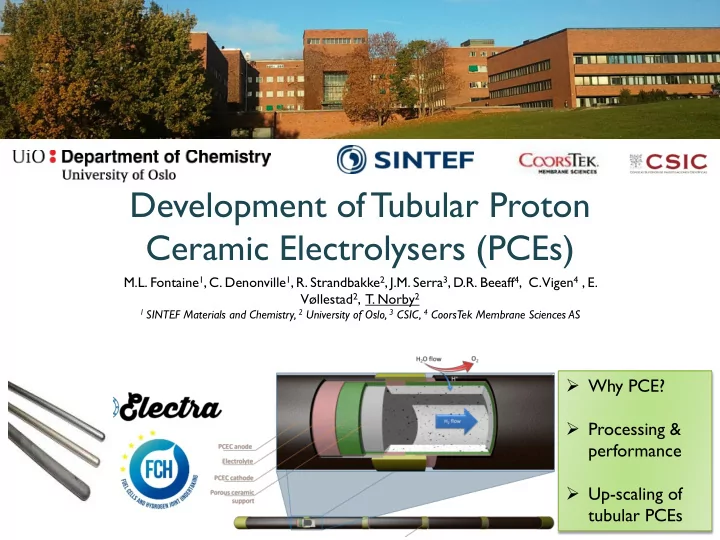
Development of Tubular Proton Ceramic Electrolysers (PCEs)
M.L. Fontaine1, C. Denonville1, R. Strandbakke2, J.M. Serra3, D.R. Beeaff4, C. Vigen4 , E. Vøllestad2, T. Norby2
1 SINTEF Materials and Chemistry, 2 University of Oslo, 3 CSIC, 4 CoorsTek Membrane Sciences AS
- Why PCE?
- Processing &
performance
- Up-scaling of