
SLIDE 1
The Aerospace & Defense Forum Dallas – Ft. Worth Chapter May 11, 2017 1
Design Considerations for Electrical Wiring Interconnect Systems in Drones
Manuel Lozano
Applications Engineer Manager / Central Region
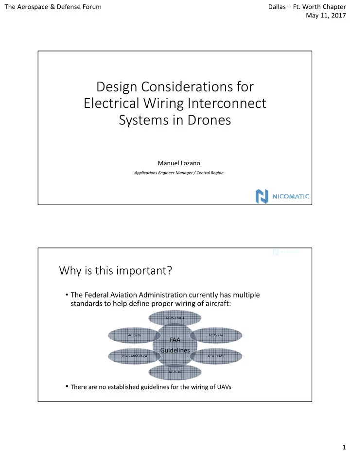
Why is this important?
- The Federal Aviation Administration currently has multiple
standards to help define proper wiring of aircraft:
FAA Guidelines
AC 25.1701-1 AC 25.27A AC 25-16 Policy ANM-01-04 AC 43.13-1b AC 25-10
- There are no established guidelines for the wiring of UAVs