
SLIDE 1
Overview: HotEnd
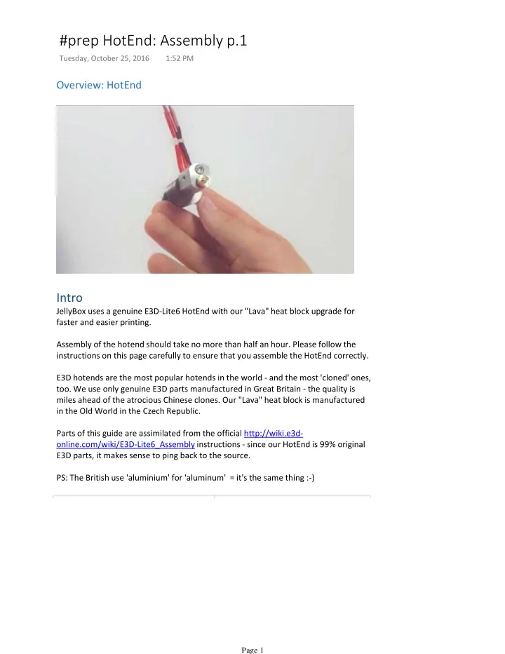
Intro
JellyBox uses a genuine E3D-Lite6 HotEnd with our "Lava" heat block upgrade for faster and easier printing. Assembly of the hotend should take no more than half an hour. Please follow the instructions on this page carefully to ensure that you assemble the HotEnd correctly. E3D hotends are the most popular hotends in the world - and the most 'cloned' ones,
- too. We use only genuine E3D parts manufactured in Great Britain - the quality is
miles ahead of the atrocious Chinese clones. Our "Lava" heat block is manufactured in the Old World in the Czech Republic. Parts of this guide are assimilated from the official http://wiki.e3d-
- nline.com/wiki/E3D-Lite6_Assembly instructions - since our HotEnd is 99% original
E3D parts, it makes sense to ping back to the source. PS: The British use 'aluminium' for 'aluminum' = it's the same thing :-)
#prep HotEnd: Assembly p.1
Tuesday, October 25, 2016 1:52 PM Page 1