
SLIDE 1
1
Data$Conversion ADC$and$DAC (aka$A/D$&$D/A)
2
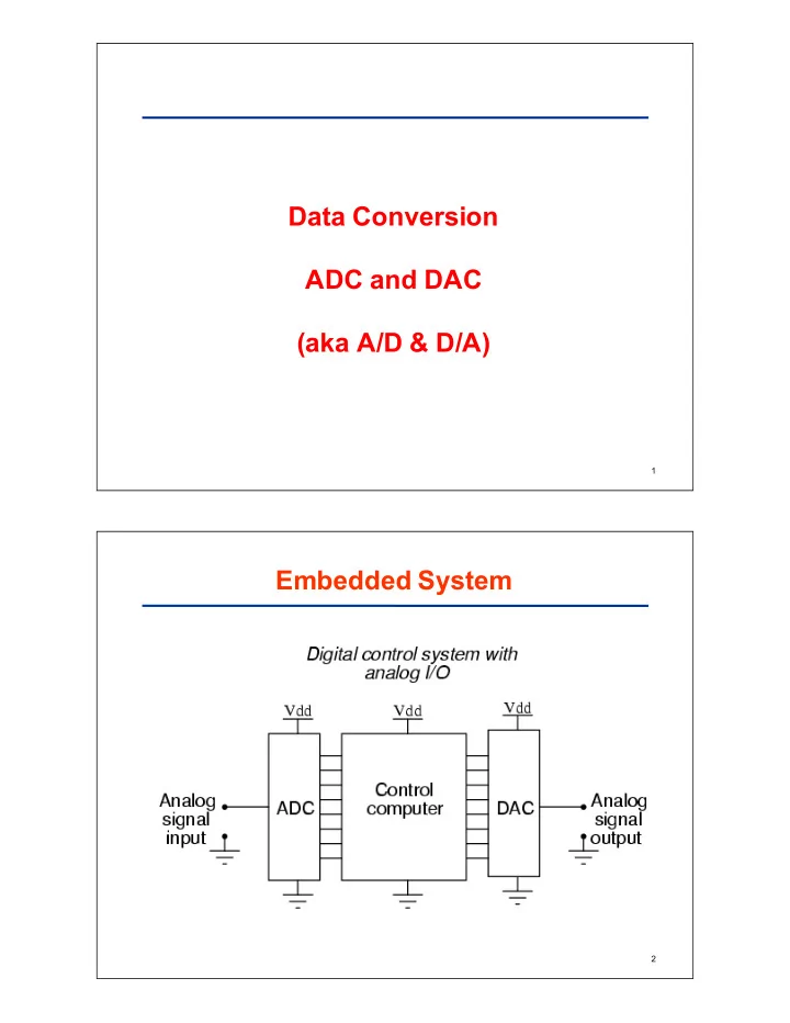
Data$Conversion ADC$and$DAC (aka$A/D$&$D/A) 1 Embedded$System - - PDF document
Data$Conversion ADC$and$DAC (aka$A/D$&$D/A) 1 Embedded$System 2 Signal$Conversion$System Analog+to+Digital Digital+to+Analog Conversion+of+Sensor+ Conversion+of+Binary+ Output+to+Binary+Code Code+to+Analog+Signal 3
1
2
3
4
5
6
7
8
9
10
11
12
13
14
15
16
17
18
19
20
21
22
23
24
25
26
27
28
29
30
31
32
33
34
35
36
37
38
39
40
41
42
43
44
45
46
47
48
49
50
2R||2R=R R+R=2R SUMMER
51