
SLIDE 1
1
CS640: Introduction to Computer Networks
Aditya Akella Lecture 15 TCP – II - Connection Set-up and Congestion Control
2
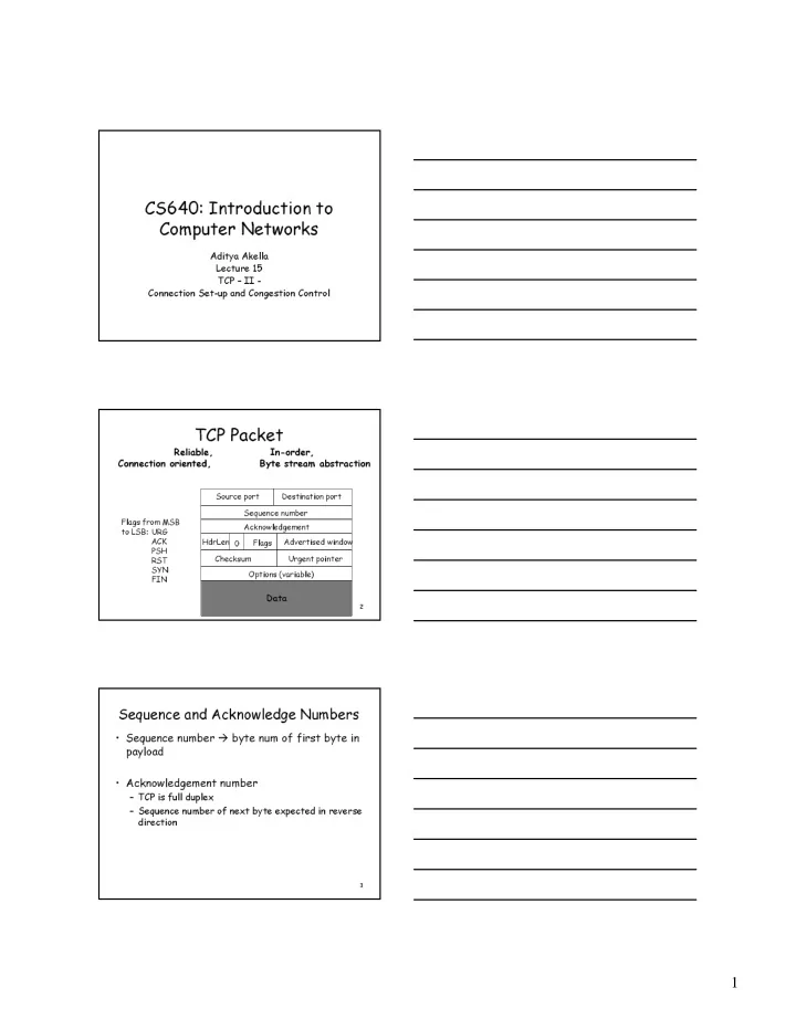
TCP Packet
Source port Destination port Sequence number Acknowledgement Advertised window HdrLen Flags Checksum Urgent pointer Options (variable)
Data
Flags from MSB to LSB: URG ACK PSH RST SYN FIN
Reliable, In-order, Connection oriented, Byte stream abstraction
3
Sequence and Acknowledge Numbers
- Sequence number byte num of first byte in
payload
- Acknowledgement number