Core Network Connects MAN networks together Requires high - - PowerPoint PPT Presentation

core network
SMART_READER_LITE
LIVE PREVIEW

Core Network Connects MAN networks together Requires high - - PowerPoint PPT Presentation

Lic.(Tech.) Marko Luoma (1/37) Lic.(Tech.) Marko Luoma (2/37) Core Network Connects MAN networks together Requires high bandwidth technologies with long range passive operation Transmission speed and distance without repeaters tend


slide-1
SLIDE 1

Lic.(Tech.) Marko Luoma (1/37)

S-38.192 Verkkopalvelujen tuotanto S-38.192 Network Service Provisioning Lecture 2: Core Network Technologies

Lic.(Tech.) Marko Luoma (2/37)

Core Network

  • Connects MAN networks together
  • Requires high bandwidth technologies with long range passive operation

Transmission speed and distance without repeaters tend to be inversely proportional 1Gbps Ethernet -> 80-150km in SM-fiber with ZX-transmitter 10Gbps Ethernet -> 10-40km in SM-fiber with ZX-transmitter

  • Typical medias are

Fiber (Single Mode) Radio (Microwave, Satellite)

Lic.(Tech.) Marko Luoma (3/37)

Core Network Technologies

  • High bandwidth requirements
  • Transmission speeds are jumping

up with constant rate 1995: 155Mbps (SDH/ATM) 2000: 2.4Gps (SDH) 2004: 10 Gbps (SDH/Ethernet) 2000-2004 wavelength technologies brought a new means to increase capacity DWDM CWDM

  • Frame based multiplexing

Irrespective of low layer functionality Fiber/Radio Options today are GMPLS SDH ATM Ethernet GFP

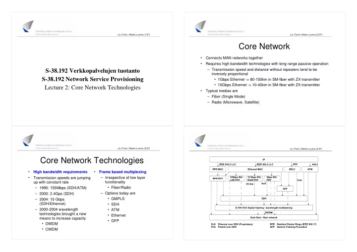
Lic.(Tech.) Marko Luoma (4/37) Dark fiber / fiber network G.709 OCh Digital framing / wavelength multiplexing SDH GFP RPR PHY 10Gbps Eth LAN PHY 10 Gbps Eth WAN PHY Gbps Eth PHY RPR MAC Ethernet MAC HDLC ATM IP AAL5 PPP IEEE 802.2 LLC IEEE 802.2 LLC PoS EoS VC-64c DWDM EoS Ethernet over SDH (Proprietary) PoS Packet over SDH RPR Resilient Packet Rings (IEEE 802.17) GFP Generic Framing Procedure

slide-2
SLIDE 2

Lic.(Tech.) Marko Luoma (5/37)

WDM

  • Optical counterpart for Frequency Division Multiplexing

Frequency

FDM Carrier

Wavelength

WDM

Lic.(Tech.) Marko Luoma (6/37)

WDM

  • Effectively N fold increase of transmission capacity from the same fiber

infrastructure Wide band components are relatively more expensive than N times narrow band components Individual lambdas can be used independently Usage depends on transponder unit Framing is in general from SDH (interface may be what ever) STM-16 – 2.4Gbps STM-64 – 10 Gbps = 10GbE STM-256 – 40 Gbps = 40GbE

Lic.(Tech.) Marko Luoma (7/37)

WDM

  • Two operative versions

CWDM – Coarse Wavelength Division Multiplexing Max 8 channels between (1470 - 1610nm with 20nm steps) DWDM – Dense Wavelength Division Multiplexing ITU Grid (100 Ghz resolution) 50 channels between 1569.80nm to 1611.79nn 50 channels between 1529.75nm to 1569.59nm 50 channels between 1491.69nm to 1529.55nm

Lic.(Tech.) Marko Luoma (8/37)

WDM

  • DWDM

Narrow channel Components need to be compensated for temperature effects Expensive More channels to choose from nonlinearities of fibers can be avoided by selecting proper wavelengths

  • CWDM

Wide channel Component requirements are looser Cheaper lasers and receivers Less channels Not suitable for long-haul networks Suitable for MANs

slide-3
SLIDE 3

Lic.(Tech.) Marko Luoma (9/37)

WDM

  • Can be used as link or network technology

Link technology Multiplexers at the ends of the links Network technology Optical switching components Optical delay lines Wavelength conversion Photonic switching

Lic.(Tech.) Marko Luoma (10/37)

WDM

  • Pros:

Protocol independent Virtual fiber Multiplexing different traffic through different wavelengths Similar failure protection than SDH networks (SDH framing)

  • Cons:

Depending on system pay as you go may not be possible The number of required channels need to be estimated for lifetime of systems Not cost effective if capacity expansion is not immediately required

Lic.(Tech.) Marko Luoma (11/37)

Synchronous multiplexing

Fixed usage of resources

Asynchronous multiplexing

Free usage of resources

Frame Multiplexing

B C A C A B D A D A B C D

D C B A D C B A D C B A D C B A D C B A C B C A D B A D A D C B A

Lic.(Tech.) Marko Luoma (12/37)

Frame Multiplexing

Synchronous

Fixed usage of resources Information does not need L2 addresses Wastes resources if communication is not CBR Easy to integrate SDH

Asynchronous

Free usage of resources Information requires L2 addresses Does not waste resources Requires additional logics to control resource usage ATM, Ethernet

slide-4
SLIDE 4

Lic.(Tech.) Marko Luoma (13/37)

SDH

  • Synchronous frame based multiplexing of transmitted signals

Link framing is done with 2430 byte frames Generation interval is 125us -> reflects the original coding of speech with 8kHz sampling rate Datarate = 155,52Mbps

1 2 3 4 5 6 7 8 9 10 11 ? 264 265 266 267 268 269 270 271 272 273 274 275 276 277 278 279 280 281 ? 534 535 536 537 538 539 540 541 542 ? 809 810 811 812 ? 1079 1080 1081 1082 ? 1349 1350 1351 1352 ? 1619 1620 1621 1622 ? 1889 1890 1891 1892 ? 2159 2160 2161 2162 ? 2429 2430

SOH (9-tavua) VC-4 (261-tavua)

Lic.(Tech.) Marko Luoma (14/37)

P O H Content

SDH

  • Link frames contain virtual containers which carry the actual

information Header information (POH) Flow and error control information between edge devices Content Virtual containers form point-to-point permanent connections through SDH network

Lic.(Tech.) Marko Luoma (15/37)

SDH

  • SDH hierarchy makes possible to use multiples and fractions of basic

rate Multiples are generated by injecting multiple (factor of four) link frames within time-slot STM-1: 155.52 Mbit/s (basic rate) STM-4: 622.08 Mbit/s (first multiplex) STM-16: 2488.32 Mbit/s (second multiplex) STM-64: 9953.28 Mbit/s (third multiplex) Operation is byte synchronous Timing of individual bytes in multiplex is same than in basic rate frame

1 1 1 1 2 2 2 2 3 3 3 3 4 4 4 4 ?

2429 2430 2430 2430 2430

Lic.(Tech.) Marko Luoma (16/37)

SDH

  • Fractions are generated by multiplexing different streams of content into

individual frame Several virtual containers destined to same or different points in network Multiplexing is done with byte interleaving

TUG-2 STM-N AUG AU-4 VC-4 C-4 TUG-3 TU-3 VC-3 C-3 TU-2 VC-2 C-2 TU-12 VC-12 C-12

140M 45M 34M 6M 2M

Osoittimien käsittely Multipleksaus Mapitus Vaiheistus

*N *3 *7 *3

slide-5
SLIDE 5

Lic.(Tech.) Marko Luoma (17/37)

SDH

  • SDH supports also concatenation of resources

Old version – strict mode Clear channel operation (small 'c' after the virtual container type) All VC:s in different frames form a single bit stream Not feasible in SDH networks Feasible if SDH is used as a point to point link technology New version – flexible mode Concatenation is used only in edge devices Supports SDH networks Concatenated VC:s need not be with same speeds Even over different fibers

Lic.(Tech.) Marko Luoma (18/37)

SDH

  • Terminal multiplexer

Responsible of taking non- SDH and lower rate SDH traffic in and interleave them in STM-N frames. Vice versa on other end of the path Each incoming traffic component has its own virtual container (routed separately within SDH network)

STM-N A K Lic.(Tech.) Marko Luoma (19/37)

SDH

  • Add-drop multiplexer

Basic component in ring type SDH networks Most of traffic passes through the ADM on ring interfaces Some traffic is taken out of ring and/or inserted into the ring

Lic.(Tech.) Marko Luoma (20/37)

SDH

  • Digital Cross Connect

Switches SDH traffic Between fibers From individual STM frame to other Basic component on mesh type networks

slide-6
SLIDE 6

Lic.(Tech.) Marko Luoma (21/37)

SDH

  • IP can not be used directly with SDH

Packet over Sonet (PoS) is method for delivering IP packets in SDH Additional framing IP packet into PPP-packet PPP packet into HDLC frame HDLC frame into SDH virtual container

IP packet VC-x data HEADER HDLC-Data Address (0xFF) Control (0x03) PPP-Data Protocol N x HDLC frame Padding FCS (CRC-32) 0x7E 0x7E

Lic.(Tech.) Marko Luoma (22/37)

SDH

  • Pros:

Optimized for TDM services (large income from leased line services) Fully compatible with metro ring networks (SDH ADM rings) Reliable and fast failure recovery (roughly 50ms with APS) Price of SDH continuously coming down

  • Cons:

Not cost effective for burst data traffic Capacity in SDH network can only be allocated on multiples of 2Mbps No multiple QoSs for different service charges Expensive interfaces at routers

Lic.(Tech.) Marko Luoma (23/37)

ATM

  • Asynchronous frame based multiplexing
  • Capabilities for dynamic switching

Not only PVP's or PVC's

  • Connection oriented
  • Fixed packet structure

5 bytes of headers Addresses (VPI, VCI) Packet content type (PT) Priority (CLP) Checksum (HEC) 48 bytes of data

HEC CLP VCI VCI VPI VPI PT VCI DATA

Lic.(Tech.) Marko Luoma (24/37)

ATM

  • Header fields define

Connection Multiplexing group

MEDIA VP VC

HEC CLP VCI VCI VPI VPI PT VCI DATA

slide-7
SLIDE 7

Lic.(Tech.) Marko Luoma (25/37)

ATM

  • Can be used

As is over the transmission media Assumes low bit error ratio from the media Over any other L2 protocol Benefits from the error control of L2 media

  • Why sensitivity to BER

Packet has not markers Delineation is accomplished through state-machine which goes through packet bit by bit and looks header checksum matches Sensitive to errors if high BER

Lic.(Tech.) Marko Luoma (26/37)

ATM

  • 48 byte content field is too big for voice communications

Separate protocol layers to handle Sub cell delineation Timing Sequencing Clear channel communication for video applications

DATA (depending on application and codec) DATA HEADER DATA SN SNP DATA POINTER Nx46 bytes 47 bytes

Lic.(Tech.) Marko Luoma (27/37)

ATM

  • 48 byte content field is too little for data networks

Fragmentation of data packets into multiple ATM cells Separate protocol layer to handle the fragmentation and reassembly

  • f protocol packets

DATA (max 64kB) PAD UU-info ID LEN CRC DATA HEADER Nx48 bytes

Lic.(Tech.) Marko Luoma (28/37)

ATM

  • Framing options for IP traffic in

ATM links: RFC2684: Multiprotocol Encapsulation over ATM Adaptation Layer 5 (Classical IP) Uses LLC/SNAP encapsulation of traffic within ATM adaption layer 5

IP packet PAD (0-47 octect) CPCS-UU (1 octect) CPI (1 octect) =0x00 Length (2 octect) CRC (4 octect) Source SAP =AA Frame Type =03 Ethertype =08-00 Destination SAP =AA OUI =00-00-00

AA-AA-03 -> SNAP 00-00-00 -> Ethertype 08-00 -> IPv4 AAL5 -trailer

slide-8
SLIDE 8

Lic.(Tech.) Marko Luoma (29/37)

ATM

  • Framing options for IP traffic in

ATM links: RFC2364: Point to Point Protocol over ATM Uses in AAL5 frames either raw PPP packets PPP on LLC/NLPID packets

PPP Information PAD (0-47 octect) CPCS-UU (1 octect) CPI (1 octect) Length (2 octect) CRC (4 octect) Source SAP Frame Type (UI) NLPID (PPP) Protocol ID Padding Destination SAP

LLC-otsikko Network Layer Protocol ID PPP AAL5 -trailer

Lic.(Tech.) Marko Luoma (30/37)

ATM

  • ATM network is from IP

perspective NBMA network Separate virtual connection between each and every router Large number of connections and adjacencies in routing Usually subinterface per connection

10.4.7.1 10.4.7.2 10.4.7.5 10.4.7.3 10.4.7.4 Lic.(Tech.) Marko Luoma (31/37)

ATM

  • Pros:

Easy capacity management Virtual short-cuts without routing MPLS ready Fault tolerant if ATM-level dynamic routing is used

  • Cons:

Additional layer of technology Not good for framing itself Expensive interfaces at routers Subinterface structure in networked ATM

Lic.(Tech.) Marko Luoma (32/37)

Ethernet

  • Technology has scaled to level where conventional core network

technologies are STM-64 and 10GbE are the same Even in optical interface level they are the same but ethernet is

  • nly 20% of the price

STM-256 will be the base for 40GbE 1GbE is based on fiber channel but can be multiplexed in STM-16 networks by having two independent connections

slide-9
SLIDE 9

Lic.(Tech.) Marko Luoma (33/37)

Ethernet

  • 10GbE

IEEE 802.3ae Full duplex Adjustable MAC speed 10Gb in LAN 9.29Gb in WAN Optical media SDH WAN Phy 10Gb LAN Phy

  • 1GbE

802.3z CSMA/CD + Full Duplex Optical and copper media Fiber channel Phy

Lic.(Tech.) Marko Luoma (34/37)

Ethernet

  • Possibility to build transparent LAN services

Majority of LAN networks are build with ethernet Some applications benefit from the fact that ethernet headers are preserved Possibility to have same IP subnet on both ends WAN network is transparent for ethernet network No PPP protocol in between SDH and Ethernet VLANs provide separation of users within the core Separate forwarding tables per customer If customer has own VLANs so called aggregated VLAN can be used Second VLAN header in packets within the core

Lic.(Tech.) Marko Luoma (35/37)

Ethernet

  • PoS way of doing things
  • WAN ethernet way

Avoids protocol conversion between ethernet and PPP

IP packet VC-x data HEADER HDLC-Data Address (0xFF) Control (0x03) PPP-Data Protocol N x HDLC frame Padding FCS (CRC-32) 0x7E 0x7E Ethernet header IP packet VC-x data HEADER HDLC-Data Address (0xFF) Control (0x03) N x HDLC frame FCS (CRC-32) 0x7E 0x7E Ethernet header

Lic.(Tech.) Marko Luoma (36/37)

Ethernet

  • Differencies in framing and error

recovery lower the price of Ethernet interfaces compared the same rate PoS interfaces OC-192 <-> STM-64 OC-48 <-> STM-16

Source: http://www.foundrynet.com/

slide-10
SLIDE 10

Lic.(Tech.) Marko Luoma (37/37)

Ethernet

  • Pros:

Optimized for burst data services No protocol conversion for interfacing with routers and LAN switches Plug-and-play ideology in operation

  • Cons:

Expensive and complicated to support the TDM voice and leased line services Poor in trouble isolation and network recovery Spanning tree operation takes tens of seconds to recover the networks IEEE802.17 (Resilient Packet Ring) and BFD (Bi-directional Forwarding Detection) will eventually help this