
SLIDE 1
| 1 | harris.com
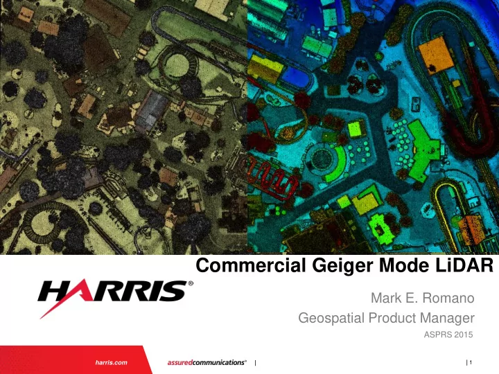
Commercial Geiger Mode LiDAR
Mark E. Romano Geospatial Product Manager
ASPRS 2015
Commercial Geiger Mode LiDAR Mark E. Romano Geospatial Product - - PowerPoint PPT Presentation
Commercial Geiger Mode LiDAR Mark E. Romano Geospatial Product Manager ASPRS 2015 | | 1 harris.com Geiger-mode (GmAPD) LiDAR sensor Geiger-mode GmAPD LiDAR Sensor Built specifically for wide-area, high-density collection | | 2 Dispelling
| 1 | harris.com
ASPRS 2015
| 2 |
Geiger-mode GmAPD LiDAR Sensor
| 3 |
False - it been utilized successfully in the defense industry for over 15 years. It is only new to the commercial industry.
Key components could not be sourced for commercial application until recently
False - in its raw (unprocessed) state it is noisier than linear systems however, this just means a different approach to processing is utilized to produce elevation data and derivative products.
False – Commercial Geiger mode technology is designed to work in daylight (solar) conditions with a minimal decrease in performance.
| 4 |
| 5 |
Harris Geiger –mode Specifications Mission Altitude range (AGL) 7,000 - >30,00 ft Flight Speed 200 - 450knots Swath Width >20,000 ft Palmer Scanner Scan Half Angle 15o Aperture Diameter 27 cm Transmit Laser Wavelength 1064 nm (Class IV) Average Power 20 W Pulse Width 550 ps Pulse Repetition Frequency 50 kHz NOHD/ENOHD 300m/2.2 km GmAPD Receiver Array Size 32 x 128 IFOV 35 urads PDE 30% Timing Resolution 250-500ps
Coverage Rate (w 50% overlap) 4 points per m2 1200 km2/hr 8 points per m2 1000 km2/hr 20 points per m2 700 km2/hr
High-sensitivity Low-power system Higher-resolution More accurate data Large-aperture Palmer scanner Multi-pulse-in-the-air Automatic range gate control Improved range separation Improved foliage penetration
| 6 |
| 7 |
Approximately 500KHz for single scanner designs
| 8 |
200MHz vs. 500KHz
| 9 |
Geiger-mode sensors sample the same spot on the ground multiple times
| 10 |
| 11 |
8 points/m2 Collection Current Linear Mode Flash (Linear Array) Photon Counting PMT Harris Geiger-mode Sensors Altitude (AGL) 150 - 1500m 500-2000m 1000-8500m 4000-11000m Field of View 45-60o 5-10o 10-40o 30o Flight Speed 50-100 kn 200-250 kn 100-200kn 200-450kn Laser Power 200-500mW 120-400mW 1-2W 20-40W PDE N/A N/A 10-15% 25-40% Pulse Width (Resolution) 1 - 10 ns 5 - 10 ns 700-900ps 300-600ps Timing Jitter (Precision) 50-500ps 50-500ps 50-100ps 250-500ps Pulse Repetition Frequency 100 - 800kHz 20-30Hz 20-35kHz 50-90kHz Detector Count less than 10 16k 100 4096 Ground Samples/Second 100k-800k 325k-500k 200-350k 200M-400M Return Surface(s) 1,4,Full Waveform 1, Multiple Multiple Multiple Area Coverage Rate (w/ desired overlap) 50-180km2/hour 40-160km2/hour 170-500km2/hour 1000-1600 km2/hour Operational Maturity 20-25 years of airborne
Improvements Limited operations in airborne mapping; Technology undergoing incremental improvement < 5 years in experimental mapping operations; Emerging technology undergoing rapid improvement 5-10 years in defense operations mapping hundreds of thousands of km2; Over 15 years in experimental use; Emerging technology undergoing rapid improvement
| 12 | 1 2 4 6 8 10 12 14 16 18 20 25 30 35 40 45 50 60 70 80 90 100
Efficiency gains keep costs down at higher collection densities
Collection Cost Collection Density (points per square meter) Linear Systems Geiger-mode
| 13 |
| 14 |
8 pts/m2
20 pts/m2 8 pts/m2 2 pts/m2 2 pts/m2
20 pts/m2 8 pts/m2
| 15 |
| 16 | NON-Export Controlled Information |
| 17 | |
| 18 |
| 19 |
| 20 |
|
| 21 |
Multi-Swath Alignment via Sensor Based 3D Photogrammetric Bundle Adjustment Enables Rigorous Accuracy Statements per Point
| 22 |
|
| 23 |
Ground Processing Workflow Raster Products
GeoTIFF
Point Cloud Products
Attributed LAS
Point Cloud Generation
Point Cloud Auto Classification
Data Finishing
QC Graphic & Metric Generation
QC Products
GeoTIFF & PNG
Preprocessing & Calibration Data Management & Archive Ingest & Project Setup
Sensor
Control
Point Cloud Generation
Hydro Enforcement Clean Up QC Analysis
Point Cloud Processing
Batch Gridding, Re-Tile & Format
Sensor Based Swath Registration Noise Filter Single Swaths Noise Filter Cross Swath Aggregate
QC Products
Match Point Filter Manual Registration Aggregate Chips to Ground Survey
Final Product Intermediate Point Clouds
| 24 |
| 25 |
“Unnamed Photogrammetrist”
Charles Dickens
| 26 |
Examples from new Harris commercial Geiger Mode LiDAR