CASE STUDY - GEOHAZARD INVESTIGATION FOR OFFSHORE DRILLING SITES - - PDF document

case study geohazard investigation for offshore drilling
SMART_READER_LITE
LIVE PREVIEW

CASE STUDY - GEOHAZARD INVESTIGATION FOR OFFSHORE DRILLING SITES - - PDF document

8/6/2020 Webinar on CASE STUDY - GEOHAZARD INVESTIGATION FOR OFFSHORE DRILLING SITES Denny Tami, Ph.D 5 th June 2020, 5pm (India) / 730pm (KL) Organised by: Dr. Parthasarathy Chairman of the Indian Geotechnical Society (IGS) - Bengaluru


slide-1
SLIDE 1

8/6/2020 1

CASE STUDY - GEOHAZARD INVESTIGATION FOR OFFSHORE DRILLING SITES

Denny Tami, Ph.D

5th June 2020, 5pm (India) / 730pm (KL)

Webinar on Organised by:

  • Dr. Parthasarathy

Chairman of the Indian Geotechnical Society (IGS) - Bengaluru Chapter

Webinar ID: 856 4942 2593 - Password: 888306

A summary of the presentation on this page Webinar Overview

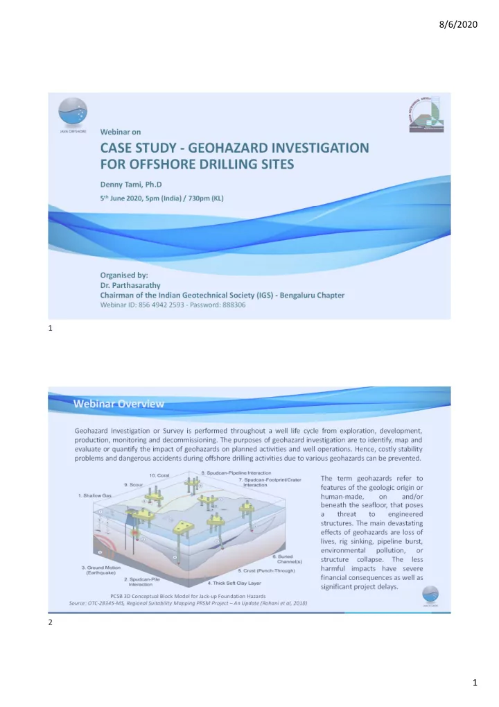
Geohazard Investigation or Survey is performed throughout a well life cycle from exploration, development, production, monitoring and decommissioning. The purposes of geohazard investigation are to identify, map and evaluate or quantify the impact of geohazards on planned activities and well operations. Hence, costly stability problems and dangerous accidents during offshore drilling activities due to various geohazards can be prevented. The term geohazards refer to features of the geologic origin or human-made,

  • n

and/or beneath the seafloor, that poses a threat to engineered

  • structures. The main devastating

effects of geohazards are loss of lives, rig sinking, pipeline burst, environmental pollution,

  • r

structure collapse. The less harmful impacts have severe financial consequences as well as significant project delays.

PCSB 3D Conceptual Block Model for Jack-up Foundation Hazards Source: OTC-28345-MS, Regional Suitability Mapping PRSM Project – An Update (Rohani et al, 2018)

1 2

slide-2
SLIDE 2

8/6/2020 2

  • Dr. Denny Tami

02 03

25-year experience in geotechnical field Current role & responsibility Personal Info

  • Indonesian / Singapore PR
  • BSc in Civil (ITB 1995, cumlaude); MSc (ITB 1998, cumlaude); Ph.D (NTU Singapore 2003)
  • 5 years at Bandung Institute of Technology, Indonesia
  • 3 years at Nanyang Technological University, Singapore
  • 4 years at CSC Piling Specialist, Singapore
  • 6 years at Fugro, Singapore
  • 7 recent years at Java Offshore, Singapore - KL - Jakarta
  • VP | GeoConsulting – Java Offshore

About the Presenter

Organizer Java Offshore

Suppo pport and Perm d Permis issio sion f from t the Ma e Manag nagement Assist stance i ce in revi viewi ewing o g of the s slides es

Source of materials

Clie ients’ s’ d data ta Previo ious us e empl ployers

  • yers a

and colleague ues In Internet

Participants

Dr

  • Dr. Parthasar

asarath athy Chairma rman o

  • f the Indian G

Geotech

  • technica

nical S Societ ety ( y (IGS) - ) - Benga galuru ru C Chapter ter

for for the the tim time an and d the the atte attentio ion

Acknowledgments

3 4

slide-3
SLIDE 3

8/6/2020 3

JAVA OFFSHORE - Brief Introduction

Established in 2012 from:

  • Earlier incorporation of PT Offshore Works Indonesia in 2010
  • Acquiring of Asian Geos Sdn Bhd in 2017

Java Offshore owns and operates:

  • 7 dedicated geophysical and geotechnical vessels
  • > 120 skilled permanent team members.
  • > 80 contract staff operating.
  • ISO 9001:2015;
  • ISO 14001:2015;
  • OHSAS 18001:2007 Certified

Who we are? What we do?

5 6

slide-4
SLIDE 4

8/6/2020 4

A summary of the presentation on this page

What to expect from this webinar:

Survey Design (planning for survey) Geophysical Survey (for non-specialist) Geohazard Assessment Case Studies (drilling related) Geotechnical Investigation (shallow water regime) Geotechnical Engineering Case Studies ( drilling sites)

  • Understanding the need both Geophysical & Geotechnical surveys
  • Sharing case studies, related to geohazard in offshore drilling sites

Outline & Objective

Survey Design (planning for survey) Geohazard Assessment (drilling related) Offshore Geotechnical Engineering (drilling sites) Geotechnical Investigation (shallow water regime) Geophysical Survey (for non-specialist)

7 8

slide-5
SLIDE 5

8/6/2020 5

A summary of the presentation on this page

#2: Obtain ground parameters:

  • Leg Penetration Analysis & Other Designs
  • Punch through & Rapid uncontrolled leg run
  • Location approval

#1: Control of ground risk:

  • Blowout, due to Shallow Gas
  • Deep / Uneven / Slow spudcan

penetration

  • Shallow Water Flows

Why perform Survey? A summary of the presentation on this page What Geohazard for Drilling Site is?

Source: Regional Suitability Mapping PRSM Project – An Update (Rohani et al, 2018)

9 10

slide-6
SLIDE 6

8/6/2020 6

A summary of the presentation on this page Lifecycle Of Offshore Facilities

Survey needed in almost each phases

Site Survey for Exploration Wells Site Survey for FEED Site Survey for Rig Revisit Site Survey for DeCom

When to Conduct Survey? A summary of the presentation on this page Which factors need to considere?

Stand Alone or Combined/Integrated Investigation?  Mode o Mode of Op Opera eratio tions, T , Type pe of Vessel Vessel Objectives of the Investigation?  Type o pe of S Survey & vey & Me Method

  • d

Environment, Water Depth (Where the Location is)?  Survey S ey System, T stem, Techni chniques, S ques, Safety fety Regulations, Standards, Permits, Code of Practices for Marine Activities?  Specifications, ifications, S Safety, fety, L Legal l & & Financial nancial C Conseq nsequences uences

11 12

slide-7
SLIDE 7

8/6/2020 7

A summary of the presentation on this page Industry Legislation, Regulations, Guidelines?

(including STANDARDS, PRACTICES, PERMITS)

International / Local Maritime Standards (IMO, IMCA, UKOOA, MIGAS, BP MIGAS, etc.) International (Offshore) Oil and Gas Industry Standards and Code of Practices (API, DNV, SNAME, etc.) International Soil Mechanics/Geotechnical/Geophysical Standards and Code of Practices (ASTM, BS, IAGC, etc.) Local Permits that Vary from Country to Country (Operating, Immigration, Customs/Import and Re-Export, Security Clearance, Dispensation, Work Permits, etc.)

Survey Design (planning for survey) Geohazard Assessment (drilling related) Offshore Geotechnical Engineering (drilling sites) Geotechnical Investigation (shallow water regime) Geophysical Survey (for non-specialist)

13 14

slide-8
SLIDE 8

8/6/2020 8

A summary of the presentation on this page

Geophysical site survey for Drilling Site typically consists of:

  • 1. Echo Sounding  water depth / bathymetry survey
  • 2. Sonar Systems  seabed features
  • 3. Magnetometer survey  magnetic anomalies
  • 4. Sub Bottom Profilers  ground stratigraphy
  • 5. 2D Hi-Res  shallow gas detection

SYSTEMS ARRANGEMENT – SINGLE PASS

SV Java Imperia – Indonesia Flag RV Java Insignia – Malaysia Flag MV Java Istoria – Malaysia Flag SV Java Ilena – Indonesia Flag

JAVA OFFSHORE’s Dedicated Geophysics Survey Vessels

15 16

slide-9
SLIDE 9

8/6/2020 9

A summary of the presentation on this page

  • 1. WATER DEPTH / BATHYMETRY EXAMPLES

A summary of the presentation on this page 2/3. SIDE SCAN SONAR IMAGES

  • Identify Objects

– Pipelines & cables – Wrecks – Debris – Seafloor topography

  • Rocks
  • Sand waves
  • Spudcan Footprints
  • Scars (trawling) and Ice Scouring
  • Pockmarks
  • Seabed Sediments

– High Backscatter

  • Gravel and coarse sands

– Medium Backscatter

  • Fine to Medium Sands

– Low Backscatter

  • Clays and silts

17 18

slide-10
SLIDE 10

8/6/2020 10

A summary of the presentation on this page

  • 4. SUB-BOTTOM PROFILERS (SBP)

Sparker Boomer Pinger SBP image removed

A summary of the presentation on this page PENETRATION vs FREQUENCY

19 20

slide-11
SLIDE 11

8/6/2020 11

Survey Design (planning for survey) Geohazard Assessment (drilling related) Offshore Geotechnical Engineering (drilling sites) Geotechnical Investigation (shallow water regime) Geophysical Survey (for non-specialist)

A summary of the presentation on this page Case 1: Deep / Uneven Spudcan Penetration, due to buried channel(s) Case 2: Coral Case 3: Well at Active Seismicity Zone Case 4: Shallow gas Case 5: Crust Layer, potential punchtrough

21 22

slide-12
SLIDE 12

8/6/2020 12

Survey Design (planning for survey) Geohazard Assessment (drilling related) Offshore Geotechnical Engineering (drilling sites) Geotechnical Investigation (shallow water regime) Geophysical Survey (for non-specialist)

Discussion & AOB Recall: Why need to do surveys:

#2: Obtain ground parameters #1: Control of ground risk

23 24

slide-13
SLIDE 13

8/6/2020 13

Discussion & AOB Basic Soil Parameters Required for LPA (Leg Penetration Analysis) Sand

Grain size Grain size Relative Density Relative Density Max/Min Density Max/Min Density Friction Angle Friction Angle

Clay

Grain Size Grain Size Atterberg Limits Atterberg Limits Water Content Water Content Unit Weight Unit Weight Undrained shear strength Undrained shear strength Remoulded shear strength Remoulded shear strength

Main Purposes: To Obtain Soil Geotechnical Parameters Discussion & AOB Methods of Offshore Geotechnical Investigation

Seabed based Downhole in drill pipe

downhole system (drilling): penetration depth 250 m possible seabed systems: penetration depth typically 6-12m but can be as deep as 40m in very soft deposit 5.5 ton Seabed CPT 2000m

25 26

slide-14
SLIDE 14

8/6/2020 14

Discussion & AOB Downhole Mode - Drilling Equipment

RV Java Illithyia – Malaysian Flag Miclyn Grace – Malaysian Flag

Discussion & AOB Which Vessel to use?

27 28

slide-15
SLIDE 15

8/6/2020 15

Discussion & AOB ONBOARD LABORATORY

  • 1. MV Test
  • 2. Sample Extrusion
  • 4. Torvane & PP tests
  • 3. Cutting of sample
  • 7. Moisture content test
  • 5. Visual description
  • 8. UU Triaxial
  • 6. Photograph

Discussion & AOB SOIL CONDITIONS

Results of Geotechnical Survey

Starboard Bow Port

Borehole Plan

Boring Logs (client data) removed

29 30

slide-16
SLIDE 16

8/6/2020 16

Survey Design (planning for survey) Geohazard Assessment (drilling related) Geotechnical Engineering (Jack-up Leg Penetration Analysis) Geotechnical Investigation (shallow water regime) Geophysical Survey (for non-specialist)

Discussion & AOB JACK-UP RIG DETAILS

Parameter Required for Leg Penetration Analysis

  • Area: 150.6 m2
  • Equivalent diameter: 13.80 m
  • Tip below widest section: 1.86 m
  • Volume: 225 m3

Spudcan Details: Spudcan Details:

  • Lightship Weight: 44.6
  • Maximum preload: 77.5 MN

Intended Load: Intended Load:

Spudcan ~15-20 m

31 32

slide-17
SLIDE 17

8/6/2020 17

Discussion & AOB Leg Penetration Analysis (LPA) - Failure Mechanisms

ref: SNAME (2008) & ISO (2012) General shear failure (both in layered- as in homogenous soil) Punch-through Squeezing Combination of the above

Notes:

  • Formula for each failure mechanism is given in

SNAME or ISO.

  • Need to understand which mode of failure, given the

actual (soil and spudcan) conditions, most likely to

  • ccur and apply the formula accordingly.

Discussion & AOB Why Worry About Punch-through ?

Consequential costs of US$1 to US$10 million per failure (source: internet)

33 34

slide-18
SLIDE 18

8/6/2020 18

Discussion & AOB Case 1: Punch Through, due to inaccurate selection of Soil Parameters

  • Simplification in necessary, but careful on the critical details
  • Always be cautious when observe hard layers or lenses in soft clay deposit.

Case 2: Spudcan Footprint Interaction: penetration into existing footprints

  • Most of Leg Penetration Analysis is a one-dimensional (1D) analysis
  • But if a footprints, pipeline, foundation exist in the vicinity, it will require a three-dimensional (3D) analysis

Case 3: False-Alarm Punch Through, due to inaccurate analysis method

  • In addition of accurate soil parameters (ie, Case 1 earlier), selection of appropriate mode of failures is also

critical

  • Need good engineering judgment and cannot be relayed totally on software to calculate

Survey Design (planning for survey) Geohazard Assessment (drilling related) Geotechnical Engineering Geotechnical Investigation (shallow water regime) Geophysical Survey (for non-specialist) (Jack-up Leg Penetration Analysis)

35 36

slide-19
SLIDE 19

8/6/2020 19

A summary of the presentation on this page

for Drilling Site / Rig Entry

Summary - Marine Geophysical and Geotechnical Services

Geophysics Geotechnics

  • 1. Purposes
  • 2. Scope
  • 3. Results

Collect subsurface data qualitatively

 define any hazard  selection of well

location

Collect subsurface data qualitatively

 define any hazard  selection of well

location

Analogue and 2D High Resolution

Survey from 1km x 1km.. to.. 5km x 5km with line spacing of 100m

Analogue and 2D High Resolution

Survey from 1km x 1km.. to.. 5km x 5km with line spacing of 100m

Geohazard mapping  optimal wellhead

location  rig approach

Geohazard mapping  optimal wellhead

location  rig approach

Collect subsurface data quantitatively

 obtain soil parameters for geotechnical analysis  location approval

Collect subsurface data quantitatively

 obtain soil parameters for geotechnical analysis  location approval

Borehole sampling &/or CPTU

at location of each jack-up rig leg

Borehole sampling &/or CPTU

at location of each jack-up rig leg

Pilot hole, if deemed necessary to verify the

absent of shallow gas

Pilot hole, if deemed necessary to verify the

absent of shallow gas

Leg Penetration Curves  hazard for rig

emplacement  final leg penetration

Leg Penetration Curves  hazard for rig

emplacement  final leg penetration

Why Why we need we need bo both th Geo Geophysical & Geotechnica & Geotechnical surveys. veys. Simpl mplifying fying d data ta is nec necess ssary, b y, but t fail failur ure to to und unders rstand t the e da data deta details is is fata fatal

(j (jackup puncht-hrough case case)

Wron Wrong mi g mind “Engineeri ngineering i g is th the O ONLY im important pro process”:

  • Always put qualified &

experienced people

  • Soil is not

homogeneous material, need good judgment.

Perception rception t that Geop Geophysi sica cal & & Geotec echnic hnical l surveys a veys are e no not seen seen as i as impo portant by en by engineers du due e to to th the w work be being lo lower v value as as

  • ppo

pposed sed t to EP EPC C wo work. rk.

The Last but not Least

Learning Point:

37 38

slide-20
SLIDE 20

8/6/2020 20

Thank You for Listening

39