SLIDE 1 ATM*
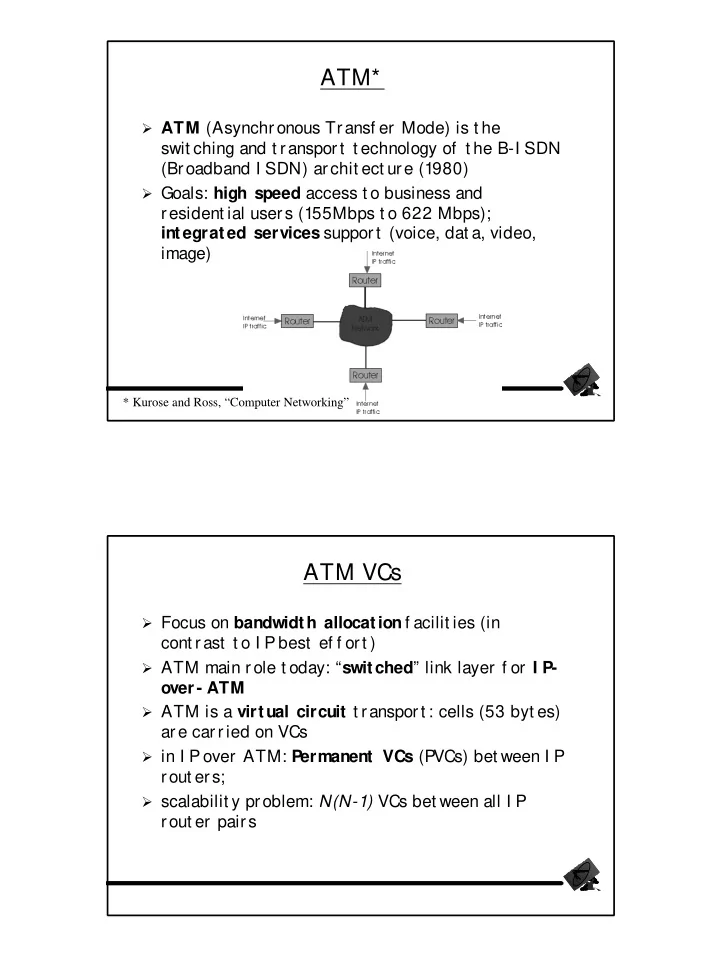
ATM (Asynchronous Transf er Mode) is t he
swit ching and t ransport t echnology of t he B-I SDN (Broadband I SDN) archit ect ure (1980)
Goals: high speed access t o business and
resident ial users (155Mbps t o 622 Mbps); integrated services support (voice, dat a, video, image)
* Kurose and Ross, “Computer Networking”
ATM VCs
Focus on bandwidth allocation f acilit ies (in
cont rast t o I P best ef f ort )
ATM main role t oday: “switched” link layer f or I P-
ATM is a virtual circuit t ransport : cells (53 byt es)
ar e car r ied on VCs
in I P over ATM: Permanent VCs (PVCs) bet ween I P
rout ers;
scalabilit y problem: N(N-1) VCs bet ween all I P
rout er pairs
SLIDE 2 ATM VCs
Switched VCs (SVCs) used f or short lived
connect ions
Pros of ATM VC approach:
- Can guarant ee QoS perf ormance t o a connect ion mapped
t o a VC (bandwidt h, delay, delay j it t er) Cons of ATM VC approach:
- I nef f icient support of datagram t raf f ic; P
VC solut ion (one P VC bet ween each host pair) does not scale;
- SVC int roduces excessive latency on short lived
connect ions
- High SVC processing Overhead
ATM Address Mapping
Rout er int erf ace (t o ATM link) has two addresses:
I P and ATM address.
To rout e an I P packet t hrough t he ATM net work,
t he I P node:
(a) inspect s own rout ing t ables t o f ind next I P router address (b) t hen, using ATM ARP table, f inds ATM addr of next rout er (c) passes packet (wit h ATM address) t o ATM layer At t his point , t he ATM layer t akes over: (1) it det ermines t he interf ace and VC on which t o send out t he packet (2) if no VC exist s (t o t hat ATM addr) a SVC is set up
SLIDE 3 ATM P hysical Layer
Two Physical sublayers: (a) Physical Medium Dependent (PMD) sublayer
- (a.1) SONET/ SDH: t ransmission f rame st ruct ure (like a
cont ainer carrying bit s);
- bit synchronizat ion;
- bandwidt h part it ions (TDM);
- sever al speeds: OC1 = 51.84 Mbps; OC3 = 155.52 Mbps;
OC12 = 622.08 Mbps
- (a.2) TI / T3: t ransmission f rame st ruct ure (old
t elephone hierarchy): 1.5 Mbps/ 45 Mbps
- (a.3) unstructured: j ust cells (busy/ idle)
ATM P hysical Layer (more)
Second physical sublayer
(b) Transmission Convergence Sublayer (TCS): it adapt s PMD sublayer t o ATM t ransport layer
TCS Funct ions:
- Header checksum generat ion: 8 bit s CRC; it prot ect s a 4-
byt e header; can correct all single errors.
- Cell delineation
- Wit h “unst ruct ured” P
MD sublayer, t ransmission of idle cellswhen no dat a cells are available in t he t ransmit queue
SLIDE 4
ATM Layer
ATM layer in charge of t ransport ing cells across
t he ATM net work
ATM layer prot ocol def ines ATM cell header
f ormat (5byt es);
payload = 48 byt es; t ot al cell lengt h = 53 byt es
ATM Layer
VCI (virt ual channel I D): t ranslat ed f rom link t o
link;
PT (P
ayload t ype): indicat es t he t ype of payload (eg mngt cell)
CLP (Cell Loss Priorit y) bit : CLP = 1 implies t hat
t he cell is low priorit y cell, can be discarded if rout er is congest ed
HEC (Header Error Checksum ) byt e
SLIDE 5 ATM Adapt at ion Layer (AAL)
ATM Adaptation Layer (AAL): “adapt s” t he ATM
layer t o t he upper layers (I P or nat ive ATM applicat ions)
AAL is present only in end systems, not in
swit ches
The AAL layer has it s header/ trailer f ields,
carried in t he ATM cell
ATM Adapt ion Layer (AAL) [more]
Dif f erent versions of AAL layers, depending on
t he service t o be support ed by t he ATM t ransport :
- AAL1: f or CBR (Const ant Bit Rat e) services such as
circuit emulat ion
- AAL2: f or VBR (Variable Bit Rat e) services such as MP
EG video
- AAL5: f or dat a (eg, I P dat agrams)
SLIDE 6 ATM Adapt ion Layer (AAL) [more]
Two sublayers in AAL:
- (Common Part) Convergence Sublayer (cpcs):
encapsulat es I P payload
- Segmentation/ Reassembly Sublayer (sar ):
segment s/ reassembles t he CPCS (of t en quit e large, up t o 65K byt es) int o 48 byt e ATM segment s
AAL5 - Simple And Ef f icient AL (SEAL)
AAL5: low overhead AAL used t o carry I P
dat agrams
- SAR header and t railer eliminat ed; CRC (4 byt es) moved
t o CPCS
AD ensures payload mult iple of 48byt es (LENGTH = P AD byt es)
- At dest inat ion, cells are reassembled based on VCI
number; AAL indicate bit delineat es t he CP CS-P DU; if CRC f ails, P DU is dropped, else, passed t o Convergence Sublayer and t hen I P
SLIDE 7 Dat agram J ourney in I P-over-ATM Net work
At Source Host:
layer f inds t he mapping bet ween I P and ATM exit address (using ARP ); t hen, passes t he dat agram t o AAL5
- (2) AAL5 encapsulates dat g and it segments t o cells;
t hen, down t o ATM I n the network, t he ATM layer moves cells f rom
swit ch t o swit ch, along a pre- established VC
At Destination Host, AAL5 reassembles cells
int o original dat g;
- if CRC OK, dat gram is passed up t he I P prot ocol.
ARP in ATM Net s
ATM can rout e cells only if it has t he ATM
addr ess
must translate exit I P address t o ATM address The I P/ ATM addr t ranslat ion is done by ARP
(Addr Recogn P rot ocol)
Generally, ATM ARP t able does not st ore all ATM
addresses: it must discover some of t hem
Two techniques:
SLIDE 8 ARP in ATM Net s (more)
(1) Broadcast t he ARP
request t o all destinations:
- (1.a) t he ARP Request msg is broadcast t o all ATM
dest inat ions using a special broadcast VC;
- (1.b) t he ATM dest inat ion which can mat ch t he I P
address ret urns (via unicast VC) t he I P / ATM address map; Broadcast overhead prohibit ive f or large ATM
net s.
ARP in ATM Net s (more)
(2) ARP Server:
- (2.a) source I P router f orwards ARP
request t o server
- n dedicat ed VC (Not e: all such VCs f rom rout ers t o ARP
have same I D)
- (2.b) ARP server responds t o source rout er wit h
I P/ ATM t ranslat ion Host s must register t hemselves wit h t he ARP
server Comments: mor e scaleable t han ABR Broadcast approach (no broadcast st orm). However, it requires an ARP server , which may be swamped wit h request s
SLIDE 9 X.25 and Frame Relay
Wide Area Net work t echnologies (like ATM); also,
bot h Virtual Circuit orient ed , like ATM
- X. 25 was born in mid ‘70s, wit h t he support of
t heTelecom Carriers, in response t o t he ARP ANET dat agram t echnology (religious war..)
Frame relay emerged f rom I SDN t echnology (in
lat e ‘80s)
Bot h X.25 and Frame Relay can be used t o carry
I P datagrams; t hus, t hey are viewed as Link Layers by t he I P prot ocol layer (and are t hus covered in t his chapt er)
X.25
X.25 builds a VC bet ween source and dest inat ion
f or each user connection
Along t he pat h, error control (wit h
ret ransmissions) on each hop using LAP-B, a variant of t he HDLC prot ocol
Also, on each VC, hop by hop f low control using
credits;
- congest ion arising at an int ermediat e node propagat es t o
source via backpressure
SLIDE 10 X.25
As a result , packet s are delivered reliably and in
sequence t o dest inat ion; per f low credit cont rol guarant ees f air sharing
Put t ing “intelligence into the network” made
sense in mid 70s (dumb t erminals wit hout TCP)
Today, TCP and pract ically error f ree f ibers f avor
pushing t he “intelligence to the edges”; moreover, gigabit rout ers cannot af f ord t he X.25 processing
As a result , X.25 is rapidly becoming extinct
Frame Relay
Designed in lat e ‘80s and widely deployed in t he
‘90s
FR VCs have no error control Flow (rate) control is end to end; much less
processing O/ H t han hop by hop credit based f low cont r ol
SLIDE 11
Frame Relay (more)
Designed t o interconnect corporat e cust omer
LANs
Each VC is like a “pipe” carrying aggregat e t raf f ic
bet ween t wo rout ers
Corporat e cust omer leases FR service f rom a
public Frame Relay net work (eg, Sprint or ATT)
Alt ernat ive, large cust omer may build Private
Frame Relay net work.
Frame Relay (more)
Frame Relay implement s most ly permanent VCs
(aggregat e f lows)
10 bit VC I D f ield in t he Frame header I f I P runs on t op of FR, t he VC I D corresponding
t o dest inat ion I P address is looked up in t he local VC table
FR swit ch simply discards f rames wit h bad CRC
(TCP ret ransmit s..)
SLIDE 12 Frame Relay -VC Rat e Cont rol
CI R = Commit t ed I nf ormat ion Rat e, def ined f or
each VC and negot iat ed at VC set up t ime; cust omer pays based on CI R
DE bit = Discard Eligibilit y bit in Frame header
- DE bit = 0: high priority, rat e compliant f rame; t he
net work will t ry t o deliver it at “all cost s”
- DE bit = 1: low priority, “marked” f rame; t he net work
discards it when a link becomes congest ed (ie, t hreshold exceeded)
Frame Relay - CI R & Frame Marking
Access Rate: rat e R of t he access link bet ween
source router (cust omer) and edge FR switch (pr ovider ); 64Kbps < R < 1,544Kbps
Typically, many VCs (one per dest inat ion rout er)
mult iplexed on t he same access t runk; each VC has
Edge FR swit ch measures t raf f ic rat e f or each
VC; it marks
(ie DE <
= 1) f rames which exceed CI R (t hese may be lat er dr opped)
SLIDE 13
Frame Relay - Rat e Cont rol
Frame Relay provider “almost ” guarant ees CI R rat e (except
f or overbooking)
No delay guarant ees, even f or high priorit y t raf f ic Delay will in part depend on rat e measurement interval Tc;
t he larger Tc, t he burst ier t he t raf f ic inj ect ed in t he net work, t he higher t he delays
Frame Relay provider must do caref ul traf f ic engineering
bef ore commit t ing t o CI R, so t hat it can back up such commit ment and prevent overbooking
Frame Relay CI R is t he f irst example of t raf f ic rat e
dependent charging model f or a packet swit ched net work