SLIDE 1 1 “How Stuff Works” Hope College Name:____________________ Mission College
AM Radio Lab
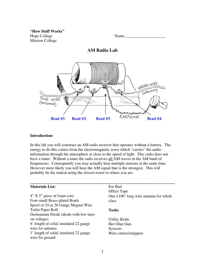
Introduction: In this lab you will construct an AM radio receiver that operates without a battery. The energy to do this comes from the electromagnetic wave which “carries” the audio information through the atmosphere at close to the speed of light. This radio does not have a tuner. Without a tuner the radio receives all AM waves in the AM band of
- frequencies. Consequently you may actually hear multiple stations at the same time.
However more likely you will hear the AM signal that is the strongest. This will probably be the station using the closest tower to where you are. ________________________________________________________________________ Materials List: 4” X 5” piece of foam core Four small Brass-plated Brads Spool of 24 or 26 Gauge Magnet Wire Toilet Paper Roll Germanium Diode (diode with low turn-
6’ length of solid, insulated 22 gauge wire for antenna 3’ length of solid, insulated 22 gauge wire for ground Ear Bud Office Tape One ≅100’ long wire antenna for whole class Tools: Utility Knife Hot Glue Gun Scissors Wire cutters/strippers Brad #1 Brad #2 Brad #3 Brad #4
SLIDE 2 2
Directions on putting Radio together:
Step 1 – Preparing the Coil
- 1. First prepare the paper tube. Draw a line along the length of the tube. Using a tack, punch a
hole in the tube about 1/2 inch from the end. Punch another hole along the line at a distance of 2 5
8 inches from the first hole.
The 2 5
8 inch distance is important so if you are not sure ask for help.
- 2. Obtain a spool of the red-colored magnet wire. Find the end of the wire.
- 3. Put the wire end through one of the holes on the outside of the tube and pull it out from the
- inside. Leave 5 inches of wire sticking out past the end of the tube.
- 4. The wire must be wound so that it is only one snug layer. The wires should touch, but
not cross or overlap on each other. As you wind after each 1/4 inch or approximately 15 turns, tape the wire with a piece of tape. This will keep the coil from unraveling if you accidentally let go.
5 inches
SLIDE 3 3
- 5. Continue winding until you reach the other hole in the tube and the coil is
2 5
8 inches long.
Tape the wire in place. Clip off the wire from the spool leaving about 5 inches. Push the leftover wire through the hole in the tube.
- 6. The last step for the coil is to prepare the ends of the wire. The wire is red because it is
coated with a varnish-like material that ensures that the electric current in the wire flows along the wire and not between the wires creating a short circuit. This coating is called the insulation. Electrical current only flows when contact is made between conductors. The red varnish insulation must be removed from the ends of the wire. Take a piece of sandpaper or a utility knife and remove the red varnish from the last 1 inch on each end of the wire. Do this very gently so the wire does not break. Make sure that the insulation is removed from all around the
- wire. When the insulation is removed you can see the copper color of the wire itself.
When the insulation has been removed, you can put the coil aside. Step 2. Earphone
- 1. Locate the earphone. Stretch out the wire. Notice the earphone wire is actually two wires
that are twisted together. At the end, unwind the two wires so that each wire end is approximately 2 inches long. Remove red insulation with sandpaper or knife From 1 inch of wire BOTH SIDES OF COIL 1 inch 2 inches
5 inches 5 inches
SLIDE 4 4 Step 3: The Diode
- 1. Locate the diode. The diode is either a small blue cylinder with a black band or a small clear
glass cylinder with a black or green band. Bend the ends of the wires as shown Step 4: Preparing the antenna and ground wires. We will need wires for an antenna and to connect the radio to the ground.
Obtain 6 feet of wire with the blue (or white) insulation. Use wire strippers to remove the insulation from each end of the wire (about 1 inch).
Obtain about 3 feet of the green insulated wire. Use wire strippers to remove the insulation from each end of the wire (about 1 inch). Note that the color of the wire does not matter to the functioning of the radio. We choose blue (or white) to remind us that the antenna wire points to the blue sky (or white clouds), and green for the ground wire to symbolize the ground. The wires could be any color as long as they are connected properly.
Wiring the Radio parts together
In steps #5 - #7 we will wire the circuit elements together by connecting the parts together using brads. Step 5: Connecting one end of the coil with the antenna and the diode. We will connect three wires together with the first brad. (This will be the left most brad when facing the radio – brad #1). The wires we will connect are: one end of the coil, the antenna, and
Wrap the antenna wire around the flat shanks of the brad tightly. Tug on the antenna to make sure wires are secure. Wrap one end of the coil around the shanks of the brad. Gently pull on the coil wire to ensure that it is firmly secured to the brad. Then locate the side of the diode opposite the stripe. The side of the diode without the stripe must connect to brad #1Loop this end of the diode around the shanks . SEE PHOTO ON NEXT PAGE
SLIDE 5 5
- f the brad as tightly as possible. Tug on the diode gently to see that it does not fall off. You
should now have three elements (the antenna, the coil, and the diode all connected to one brad. This will be brad #1. Step 6: Connect the diode with the ear phone
- 1. Tie the twisted earphone wire around a brad (brad #3). Leave enough wire to connect to the
- ther two brads. This will secure the earphone wire in place and keeps it from being pulled off
accidentally later on when you are using your radio. The earphone wires are fragile. In order to put the stress on the thicker part of the wire we will use brad#3 to hold the earphones to the base. Blue Antenna Wire Brad #1 Diode Stripe !! IMPORTANT !! Wires wrapped around brad Tie earbud wire in a know around the bard Brad #3 Leave some wire to connect later
SLIDE 6 6
- 2. Next connect one end of the earphone to Brad #2. Wrap the bare wire around the shanks of
this brad. Next wrap the wire from the side of the diode with the stripe around the shanks. Step 7: Connect the earphone with the other end of the coil and the ground wire.
- 1. At brad #4 (the right-most brad) connect three wires: the remaining earphone wire, the end of
the coil and the green-colored wire. As is the case for the three wires at brad #1, getting all of the wires around the brad at the same time can be a little tricky. Make sure the wires are secure so they do not fall off later when you are listening to your radio. Wrap tightly and make multiple turns. SEE PHOTO ON THE NEXT PAGE Brad #2 Earbud wire Wires wrapped around brad Diode Stripe
SLIDE 7 7 The radio is assembled. Now it is ready to be mounted on the foam core base. Step 9: Punch holes in the foam core where the brads will go.
- 1. Lay the radio circuit you built on top of the foam core. Mark the locations for the brads.
Punch holes in the foam core where the brads rest. Use a nail to punch the holes. Brad #4 Green Ground wire Earbud Wire Coil Wire Wires wrapped around brad
SLIDE 8
8 Step 10: Assembly Insert the four brads into the foam core and spread the shanks out on the underside. Your radio should look somewhat like the model. Nail to punch holes Brads go through holes in foamcore
SLIDE 9 9 Bend the brads on the underside of the foam core. Make sure the brads do not touch. This will cause a short circuit between connections and your radio will not work. Secure the brads with tape to the foam core. Step 8: Securing the coil to the base.
- 1. Use hot glue or double sided tape to attach the coil to the foam core base in approximately the
same position as the one in the model. The exact position of the coil on the base is not critical. Bend tabs and secure with tape Brads should not touch!!! !! IMPORTANT !! Hot Glue
SLIDE 10 10 Step 10: Testing the Radio A crystal radio is not very powerful. To make matters worse, concrete buildings tend to block
- ut radio signals so you will have to go outside to test your radio. When you are at home the
radio may work inside near a window. For now take your radio outside, attach the green ground wire to something metal like a fence, a railing, a water pipe, or a bike rack. Stretch out the
- antenna. Listen with the earphone
If you don’t hear anything a longer, horizontal antenna (wire) may be needed. . You may need to use the 100’ long antenna used by the whole class. Make sure the un-insulated ends of the antenna wire do not touch the ground as this will ground the radio wave. The radio waves are affected by the weather and time of day too.
NEVER CONNECT ANY PART OF YOUR RADIO TO A POWERLINE OR ANY SORT OF ELECTRICAL OUTLET, OR LAMP SOCKET
Bike Rack (unpainted metal) Outdoor Faucet (unpainted metal) Fence Post (unpainted metal) Metal Sink or Faucet
SLIDE 11
11
How a radio works:
Many of you may have drawn some of your own conclusions as to how a radio works. Let's see if those conclusions are right by looking at the place where the whole process starts - A radio station. An accurate mixture of sound and electricity are the two main ingredients needed to transmit and speak on the radio. The wavy line represents the loud and soft tones of what is said when an announcer is speaking into a microphone. The frequency determines pitch (high and low tones) and the amplitude determines volume of the sound. The microphone turns those loud, soft, high, and low tones into electrical impulses that correspond accurately with the announcer’s speech. A diagram of the electrical impulses would match up with the sound diagram exactly.
and are changed to electrical impulses... Sound waves go in...
At the station, an electrical device called an oscillator is producing another electrical current called an AC -Alternating current. An alternating current is a current that continually changes the direction of its flow in an electrical circuit. This current flows in one direction; then t flows in the opposite direction; then it reverses again, back and forth, many times a second. The AC produced by the oscillator alternates this way about a million times a second. Technically speaking we would say it has a frequency of about a million cycles per second or a million Hertz (Megahertz). This current could be illustrated like this:
SLIDE 12 12 When the electrical impulses from the microphone are combined with the current from the
- scillator the station’s transmitter will produce something like this:
+ =
Notice that the top half of the new current is a mirror image of the bottom half. In the top half of the diagram, the current is flowing one way; in the bottom half, it is flowing the other way. Also notice that the shape of the alternating current, called the amplitude, now varies in direct proportion with the electrical impulses from the microphone. The pattern of the announcer’s speech has been superimposed on the alternating current. Because the amplitude of the alternating current now varies, this method of radio broadcasting is called "Amplitude Modulation," or "AM" for short. (FM radio uses frequency modulation which is a different technique that involves varying the frequency of the AC). A high-frequency current, that is, a current that alternates very rapidly, has a peculiar property: it gives off radio waves which have the same frequency as the current that produced them. Radio waves can be compared to light. For example, they both spread through space at a speed
- f almost 200 thousand miles per second without needing any wires to carry them. Unlike light,
radio waves are not stopped by trees, buildings, or people. However because our eyes are not sensitive to radio signals we cannot see radio waves. The radio waves leave the radio station transmitter tower and travel outward in all directions. In radio broadcasting, this high-frequency current or flow of electricity is called the "carrier frequency" because through amplitude modulation it "carries" the announcer’s voice away from the station in the form of radio waves.
SLIDE 13
13 When the radio waves strike a long piece of wire, such as the antenna in your radio, they create an electric current. This current is a very weak copy of the transmitter current that sent out the radio waves at the station: The alternating current as shown above gets induced in the antenna and then travels to the diode. The diode is a one-way electrical switch. In other words, it only lets through electric current moving in one direction, but blocks any current moving in the opposite direction so only the "top half" of the AC current gets through as shown below: The coil works in connection with the rest of the radio to respond only to radio signals which have a carrier frequency corresponding to AM radio stations. In this way other radio signals that may also strike the antenna are filtered out. Just like a musical instrument is tuned, the coil is tuned to a particular frequency. This explains why we had to be careful to have the length of the coil close to 2 5
8 inches.
From the diode, the modified current goes to the earphone, which turns it into a sound wave having the same shape as the sound impulses in the announcer's speech. Since radio waves travel so fast, we hear the announcer's voice on our radio at almost exactly same time that the announcer speaks.
SLIDE 14
14
Electrical impulses go in... and are changed back to sound waves
The alternating electrical current then travels out of the radio through the ground wire. The alternating electrical current produced by the radio waves striking the antenna must have a place to which it can flow. The ground wire provides this by connecting the radio to the earth. That is why the wire is called the "ground wire." The current flowing out is replaced by new radio waves striking the antenna. Sometimes your body can substitute for the earth in providing a place for the current to flow. The Diode: The diode and the earphone are the only components in the radio that are not commonly found in an average hardware store. However, most consumer electronics include diodes. The diode acts as a one-way valve for electricity. This feature helps your radio process the signal broadcasted by the radio station. In the early days of radio a small crystal of lead-sulphur was used as the diode, so this type of radio was often called a "Crystal Radio." Our diode uses a small piece of the metal germanium encased in glass but the name "crystal radio” is often used to describe this type of simple radio.
SLIDE 15 15
Integration with Speaker:
Find a partner who built the speaker. Using the Audio Amplifier provided, test your radio using the homemade speaker. The amplifier should be connected after the radio’s diode. Remove the earphone and connect the amplifier. You may want to try a pre-made speaker to test the only your radio and amplifier. Questions:
- 1. What is the speed of light? What is the speed of sound? What are two big advantages of
using electromagnetic waves to carry sound information?
- 2. What does AM stand for? What does FM stand for? When listening to
KQED FM what does the ’88.5’ mean?
- 3. Why does the radio not work if there is not good connection to ground?
- 4. Make a circuit drawing of your radio showing the various components. Be sure to show
the diode and on which side the stripe is located. The drawing should be detailed enough so that you could use it to fix your radio if one of the parts were to come off.
- 5. Try your radio at home in at least 5 different places. Several places to try are mentioned
in the lab write-up. REMEMBER TO NEVER CONNECT ANY PART OF YOUR RADIO TO AN ELECTRICAL OUTLET. Make a table of the locations and indicate what the antenna and ground wires were connected to (if anything). Indicate whether or not you were able to hear anything. Where does the radio seem to work best? Under what conditions? (night, fog, daytime, etc.)
Audio Amplifier
9 Volts Antenna Diode Ground
SLIDE 16 16 Did you make any interesting or puzzling observations in trying to listen to your radio at various locations?
- 6. Write a description of how the radio works. To prepare your answer use information
given in the lab, the lab write up, and other sources. Include a description of the function
- f the antenna, diode, coil, earphone, and ground.
- 7. Can this radio play FM stations? Explain why or why not.
- 8. How is it that the radio works without a battery?
Grading Rubric for #6: Response Description No attempt 1 Answer includes an accurate description of what a radio does (receives and detects AM radio waves) rather than how it works 2 Answer includes at least one accurate, but incomplete idea of how the radio works. 3 Answer includes accurate explanation of how 2 or more of the following are used in a radio: antenna, coil, diode, ground wire earphone, electromagnetic waves. 4 Answer includes accurate explanation of how 3 or more of the following are used in a radio: antenna, coil, diode, ground wire earphone, electromagnetic waves. 5 Accurate complete explanation: The function of all components
- f the radio are explained.