
SLIDE 1
Slide 1 / 69
Alternating Current
Slide 2 / 69 Topics to be covered
Sources of alternating EMF AC Circuits and Impedance LRC Series AC Circuits Resonance in AC Circuit Oscillations Transformers
Slide 3 / 69 Sources of Alternating EMF
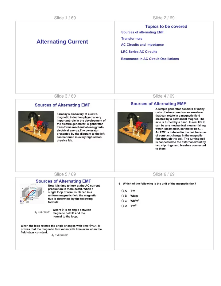
Faraday's discovery of electro- magnetic induction played a very important role in the development of the electric generator. A generator transforms mechanical energy into electrical energy.The generator presented by the diagram to the left can be found in every high school physics lab.
Slide 4 / 69 Sources of Alternating EMF
A simple generator consists of many coils of wire wound on an armature that can rotate in a magnetic field created by a permanent magnet. The axle is turned by a hand. In real life it can be any mechanical means (falling water, steam flow, car motor belt...). An EMF is induced in the coil because
- f constant change in the magnetic