Alternating Current Electricity 15-1 Frequency and Period - - PowerPoint PPT Presentation

alternating current electricity 15 1
SMART_READER_LITE
LIVE PREVIEW

Alternating Current Electricity 15-1 Frequency and Period - - PowerPoint PPT Presentation

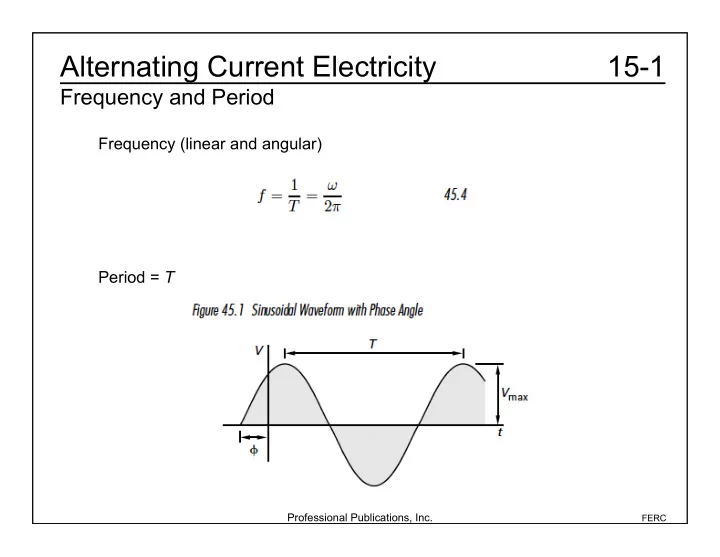
Alternating Current Electricity 15-1 Frequency and Period Frequency (linear and angular) Period = T Professional Publications, Inc. FERC Alternating Current Electricity 15-2a Average Value Square wave, positive pulse = negative pulse: X ave


slide-1
SLIDE 1

Professional Publications, Inc.

FERC

15-1 Alternating Current Electricity

Frequency and Period

Frequency (linear and angular) Period = T

slide-2
SLIDE 2

Professional Publications, Inc.

FERC

15-2a Alternating Current Electricity

Average Value

Square wave, positive pulse = negative pulse: Xave = 0 Pulse pattern, positive, all the same: where t is the duration of the pulse and T is the period. Sawtooth: Xave = Symmetrical triangular wave: Xave = 0 Xave = tXmax T 1 2 Xmax

slide-3
SLIDE 3

Professional Publications, Inc.

FERC

15-2b Alternating Current Electricity

Average Value

Example (FEIM): A plating tank with an effective resistance of 100 Ω is connected to the

  • utput of a full-wave rectifier. The applied voltage is sinusoidal with a

maximum of 170 V. How long does it take to transfer 0.005 faradays? Vave = 2Vmax

  • = (2)(170 V)
  • = 108.2 V

Iave = Vave R = 108.2 V 100 = 1.082 A t = q Iave = (0.005 F) 96,487 A s F

  • 1.082 A

= 446 s

slide-4
SLIDE 4

Professional Publications, Inc.

FERC

15-3a Alternating Current Electricity

Effective or Root-Mean-Squared (RMS) Value

Effective value of an alternating waveform: For a sinusoidal waveform, For a half-wave sinusoidal waveform, Pulse pattern, positive, all the same: where t is the duration of the pulse and T is the period. Symmetrical triangular: Sawtooth: Xrms = t T Xmax Xrms = 1 3 Xmax Xrms = 1 3 Xmax

slide-5
SLIDE 5

Professional Publications, Inc.

FERC

15-3b Alternating Current Electricity

Effective or Root-Mean-Squared (RMS) Value

Example 1 (FEIM): A 170 V (maximum value) sinusoidal voltage is connected across a 4 Ω

  • resistor. What is the power dissipated by the resistor?

Vrms = Vmax 2 = 170 V 2 = 120.2 V P = Vrms

2

R = 120.2 V

( )

2

4 = 3.6110

3 W

slide-6
SLIDE 6

Professional Publications, Inc.

FERC

15-3c1 Alternating Current Electricity

Effective or Root-Mean-Squared (RMS) Value

Example 2 (FEIM): What is the Irms value for the following waveform? (A) (B) (C) (D) 2 4 I 3 4 I 10 4 I 3 2 I

slide-7
SLIDE 7

Professional Publications, Inc.

FERC

15-3c2 Alternating Current Electricity

Effective or Root-Mean-Squared (RMS) Value

Irms = 1 T (I(t))

2 T

  • =

1 T I

2dt + 1

T I 2

  • 2

dt

T 2 T

  • T

2

  • =

I

2

T T 2

  • + 1

T

  • I

2

4

  • T

( ) T

2 T

= I

2

2 + I

2

4T

  • T

2

  • =

I

2

2 + I

2

8 = 5 8 I

2 =

10 4 I Therefore, the answer is (C).

slide-8
SLIDE 8

Professional Publications, Inc.

FERC

15-3d Alternating Current Electricity

Effective or Root-Mean-Squared (RMS) Value

Example 3 (FEIM): A sinusoidal AC voltage with a value of Vrms = 60 V is applied to a purely resistive circuit. What steady-state voltage would dissipate the same power as the AC voltage? (A) 30 V (B) 42 V (C) 60 V (D) 85 V The answer is right in the problem statement. Since the voltage is given as an rms value, the equivalent DC voltage is simply 60 V. Therefore, the answer is (C).

slide-9
SLIDE 9

Professional Publications, Inc.

FERC

15-4 Alternating Current Electricity

Phasor Transforms

Phase angle = θ – φ φ as the angle between the reference and voltage θ as the angle between the reference and current If the phase angle is positive, the signal is called “leading” or “capacitive.” If the phase angle is negative, the signal is called “lagging” or “inductive.” If the phase angle is zero, the signal is called “in phase.”

slide-10
SLIDE 10

Professional Publications, Inc.

FERC

15-5a Alternating Current Electricity

Impedance

Definitions Impedance: Resistor: Capacitor: Inductor:

slide-11
SLIDE 11

Professional Publications, Inc.

FERC

15-5b1 Alternating Current Electricity

Impedance

Example (FEIM): For the following circuit: (a) What is the impedance in polar form? (b) Is the current leading or lagging? (c) What is the voltage across the inductor?

slide-12
SLIDE 12

Professional Publications, Inc.

FERC

15-5b2 Alternating Current Electricity

Impedance

(a) Z = 3 + j 400 1 s

  • (2.510

3 H) – j

1 400 1 s

  • (62510

3 F)

+9 40° = 3 + j1 j4 +(9 )cos40°+(j9 )sin40° = 3 + 6.894 + j(1 4 +5.785 ) = 9.894 + j2.785 Z = (9.894)

2 +(2.785) 2 = 10.28

Phase angle = tan

1 imaginary

real

  • = tan

1 2.785

9.894

  • = 15.72°

Z = 10.2815.72°

slide-13
SLIDE 13

Professional Publications, Inc.

FERC

15-5b3 Alternating Current Electricity

Impedance

(b) I = V Z = 160V0° 10.2815.72°

  • = 16.56A15.72°

Therefore, the current is lagging (ELI). (c) VL = IZL = (15.56 A 15.72°)(1 90°) = 15.56 V 74.28°

slide-14
SLIDE 14

Professional Publications, Inc.

FERC

15-6 Alternating Current Electricity

Admittance

Multiplying by the complex conjugate,

slide-15
SLIDE 15

Professional Publications, Inc.

FERC

15-7 Alternating Current Electricity

Ohm’s Law for AC Circuits

Example (FEIM): What is the current in the capacitor in the following circuits? Z = 2 j4 = 4.47 63.4° I = V Z = 180 V0° 4.47 63.4° = 40.3 A 63.4° (a) Zc = 0.25 90° I = V Zc = 180 V0° 0.25 90° = 720 A 90° (b)

slide-16
SLIDE 16

Professional Publications, Inc.

FERC

15-8a Alternating Current Electricity

Complex Power

P: real power (W) Q: reactive power (VAR) S: apparent power (VA)

  • Power Factor:
  • Real Power:
  • Reactive Power:
slide-17
SLIDE 17

Professional Publications, Inc.

FERC

15-8b1 Alternating Current Electricity

Complex Power

Example (FEIM): For the following circuit, find the (a) real power, and (b) reactive power. (c) Draw the power triangle. (a) The real power is: (b) The reactive power is: P = VR

2

R = (120 V)

2

10 = 1440 W Q = VL

2

XL = (120 V)

2

4 = 3600 VAR

slide-18
SLIDE 18

Professional Publications, Inc.

FERC

15-8b2 Alternating Current Electricity

Complex Power

(c) The power triangle is: In this example, the impedance of the inductor has a lagging Current so the current has a negative phase angle. The complex conjugate of the current has a positive phase angle, so the reactive power, Q, is positive and the power triangle is in the first quadrant. For a leading current (which has a positive phase angle compared to the voltage) the power triangle has a negative imaginary part and a negative power angle, so it is in the fourth quadrant.

slide-19
SLIDE 19

Professional Publications, Inc.

FERC

15-9a Alternating Current Electricity

Resonance

Parallel Resonance Quality Factor: Bandwidth: Half-power point is when Series Resonance Quality Factor: Bandwidth: Half-power point is when R = X: 1/2power = 0 ± 1 2BW R = X: 1/2power = 0 ± 1 2Q

slide-20
SLIDE 20

Professional Publications, Inc.

FERC

15-9b1 Alternating Current Electricity

Resonance

Example (FEIM): For the following circuit, find (a) the resonance frequency (rad/s) (b) the half-power points (rad/s) (c) the peak current (at resonance) (d) the peak voltage across each component at resonance (a) 0 = 1 LC = 1 (20010

6 H)(20010 12 F)

= 510

6 rad

s

slide-21
SLIDE 21

Professional Publications, Inc.

FERC

15-9b2 Alternating Current Electricity

Resonance

(b) 1

2power = 0 ± 1

2BW = 0 ± R 2L = 510

6 rad

s ± 50 (2)(20010

6 H)

= 5.12510

6, 4.87510 6 rad

s (c) At resonance, Z = R, I(resonance) = V R = 20 V 0° 50 = 0.4 A0° (d) VR = I0R = 0.4 A 0°

( ) 50 ( ) = 20 V 0°

VL = I0XL = I0 jL = (0.4 A 0°) 510

6 rad

s

  • (20010

6 H)90°

= 400 90° V

C = VL = 400 V 90°

slide-22
SLIDE 22

Professional Publications, Inc.

FERC

15-9c Alternating Current Electricity

Resonance

Example (FEIM): A parallel resonance circuit with a 10 Ω resistor has a resonance frequency of 1 MHz and bandwidth of 10 kHz. What resistor value will increase the BW to 20 kHz? C remains the same, so to double the BW. BW = 0 Q = 0RC = 1 RC Rnew = 1 2Rold = 5

slide-23
SLIDE 23

Professional Publications, Inc.

FERC

15-10a Alternating Current Electricity

Transformers

slide-24
SLIDE 24

Professional Publications, Inc.

FERC

15-10b Alternating Current Electricity

Transformers

Example 1 (FEIM): What is the voltage V3? Disregard losses. Therefore, the answer is (D). V2 = N2 N1 120 V V3 = N3 NA V2 V3 = N3 NA

  • N2

N1

  • 120 V

( ) = 300

100

  • 50

200

  • 120 V

( ) = 90 V

(A) 45 V (B) 65 V (C) 75 V (D) 90 V

slide-25
SLIDE 25

Professional Publications, Inc.

FERC

15-10c Alternating Current Electricity

Transformers

Example 2 (FEIM): What is the total impedance in the primary circuit? Assume an ideal transformer. Ztotal = Zp + Z = 50 100

  • 2

(12 + j4 )+3 + j = 4+3+ j(1+1) = 7+ j2

slide-26
SLIDE 26

Professional Publications, Inc.

FERC

15-11a Alternating Current Electricity

Rotating Machines

Synchronous Machines

  • 1. Synchronous motors
  • 2. Synchronous generators
slide-27
SLIDE 27

Professional Publications, Inc.

FERC

15-11b Alternating Current Electricity

Rotating Machines

Example (FEIM): A six-pole, three-phase synchronous generator supplies current with a frequency of 60 Hz. What is the angular velocity of the rotor in the generator? (A) 10 rad s (B) 40 rad s (C) 60 rad s (D) 80 rad s ns = 120f p = 60 2 = 4f p = 4 rad cycle

  • 60 cycle

s

  • 6

= 40 rad/s Therefore, the answer is (B). (Note: Here, Ω does not mean

  • hms. It is the angular velocity.)
slide-28
SLIDE 28

Professional Publications, Inc.

FERC

15-11c Alternating Current Electricity

Rotating Machines

Induction Motors

  • A constant-speed device that receives power though induction

without using brushes or slip rings Slip:

slide-29
SLIDE 29

Professional Publications, Inc.

FERC

15-11d Alternating Current Electricity

Rotating Machines

Example (FEIM): A four-pole induction motor operates on a three-phase, 240 Vrms line-to- line supply. The slip is 5%. The operating speed is 1600 rpm. What is most nearly the operating frequency? (A) 56 Hz (B) 60 Hz (C) 64 Hz (D) 102 Hz ns = n(1+s) = 1600 rpm

( )(1+0.05)

= 1680 rpm

Solving the synchronous speed equation for the operating frequency yields

f = pns 120 = 4

( ) 1680 rpm ( )

120 = 56 Hz

Therefore, the answer is (A).

slide-30
SLIDE 30

Professional Publications, Inc.

FERC

15-11e Alternating Current Electricity

Rotating Machines

DC Machines

  • Have a constant magnetic field in the stator; the magnetic field of

rotor responds to the stator field

  • The magnetic flux produced is described by the equation
slide-31
SLIDE 31

Professional Publications, Inc.

FERC

15-11f Alternating Current Electricity

Rotating Machines

DC Generators

  • A device that produces DC potential
slide-32
SLIDE 32

Professional Publications, Inc.

FERC

15-11g Alternating Current Electricity

Rotating Machines

DC Generators For the DC machine equivalent circuit Terminal Voltage: For the simplified DC machine equivalent circuit Terminal Voltage:

slide-33
SLIDE 33

Professional Publications, Inc.

FERC

15-11h1 Alternating Current Electricity

Rotating Machines

Example (FEIM): A DC generator provides a current of 12 A for a resistive load when

  • perating at 1800 rpm. The speed of the armature is reduced, and the

new steady-state current is 10 A. What is most nearly the operating speed when the generator reaches steady-state conditions? Ignore armature resistance. (A) 1500 rpm (B) 1700 rpm (C) 1800 rpm (D) 2200 rpm

slide-34
SLIDE 34

Professional Publications, Inc.

FERC

15-11h2 Alternating Current Electricity

Rotating Machines

The current is proportional to the voltage by Ohm’s law. From the equation for the armature voltage, ignoring the armature resistance, the armature voltage is proportional to the speed. Va = Kan Therefore, the armature current is proportional to the speed. I2 I1 = V2 V

1

= n2 n1 Rearranging yields the new operating speed. n2 = I2 I1 n1 Therefore, the answer is (A). = 10 A 12 A

  • (1800 rpm)

= 1500 rpm

slide-35
SLIDE 35

Professional Publications, Inc.

FERC

15-11i Alternating Current Electricity

Rotating Machines

DC Motors

  • Very similar to a DC generator, only the direction of current

changes Power (for the motor model in the DC machine equivalent circuit):

  • Ignoring the power dissipated as heat for the DC machine

equivalent circuit, Torque: Mechanical Power:

slide-36
SLIDE 36

Professional Publications, Inc.

FERC

15-11j Alternating Current Electricity

Rotating Machines

Example (FEIM): A DC motor is operating on 100 V with a magnetic flux of 0.02 Wb produces an output torque of 20 N • m. The magnetic flux is changed to 0.03 Wb. What is most nearly the new steady-state output torque? Ignore armature resistance. T

1

T2 = 1 2 T2 = 2 1 T

1

= 0.03 Wb 0.02 Wb

  • 20 Nm

( )

= 30 Nm The answer is (B). The motor voltage is not important to the solution because the torque equation is proportional to the magnetic flux. (A) = 19 Nm (B) = 30 Nm (C) = 32 Nm (D) = 51 Nm

slide-37
SLIDE 37

Professional Publications, Inc.

FERC

15-12a Alternating Current Electricity

Additional Examples

Example 1 (FEIM): For the circuit elements shown, draw the conventional impedance diagram.

slide-38
SLIDE 38

Professional Publications, Inc.

FERC

15-12b Alternating Current Electricity

Additional Examples

Example 2 (FEIM): What is the steady-state magnitude of the rms voltage across the capacitor? (A) 15 V (B) 30 V (C) 45 V (D) 60 V Z = 10 + j(15 15 ) = 10 Irms = Vrms R = 40 V 10 = 4 A Vc rms = IrmsXc = (4 A)(15 ) = 60 V Therefore, the answer is (D).

slide-39
SLIDE 39

Professional Publications, Inc.

FERC

15-12c1 Alternating Current Electricity

Additional Examples

Example 3 (FEIM): For the following circuit, the rms steady-state currents are I1 = 14.436.9° and I2 = 690°. The impedance seen by the voltage source is most nearly (A) 9.5 18.4° (B) 10.0 36.9° (C) 10.7 16.0° (D) 11.0 7.1°

slide-40
SLIDE 40

Professional Publications, Inc.

FERC

15-12c2 Alternating Current Electricity

Additional Examples

Note: The preceding calculation is an example of rationalizing the denominator of a complex number without converting it to polar form. Z = R + 1 1 Z1 + 1 Z2 = R + Z1Z2 Z1 + Z2 = 5 + (4+ j3)( j12) 4+ j3 j12 = 5 + 36 j48 4 j9

  • 4+ j9

4+ j9

  • Z = 5 +144 + 432 + j(324 192 )

16 +81 = 5 + 576 97 + j 132 97

  • = 5 +5.938 + j1.361 = 10.938 + j1.361

Z = (10.938 )

2 +(1.361) 2 = 11.0

tan

1 1.361

10.938 = 7.1° Z = 117.1° Therefore, the answer is (D).

slide-41
SLIDE 41

Professional Publications, Inc.

FERC

15-12d Alternating Current Electricity

Additional Examples

Example 4 (FEIM): The phasor form of I3 is most nearly (A) 10.3 A 32.5° (B) 11.8 A 12.9° (C) 18.6 A 51.9° (D) 18.6 A 51.9° I3 = I1 + I2 = 14.4 A 36.9°+ 6 A90° = (14.4 A)cos(36.9°)+ j(14.4 A)sin 36.9°+ j6 A = 11.515 A j8.646 A + j6 A = 11.515 A j2.646 A I3 = (11.515A)

2 +(2.646A) 2 = 11.8A

tan

  • 1 2.646A

11.515A = 12.9° I3 = 11.8A12.9° Therefore, the answer is (B).