
SLIDE 1
Active Reservoir Vent™
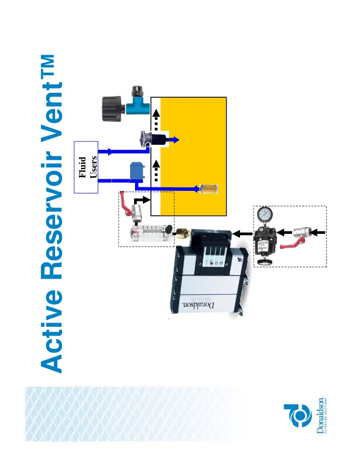
Fluid Users
Active Reservoir Vent Fluid Users Active Reservoir Vent may be - - PDF document
Active Reservoir Vent Fluid Users Active Reservoir Vent may be the right solution for you. Do you have problems with water in your oil? Does your oil analysis indicate water contamination? Does your oil analysis indicate water
Fluid Users
Does your oil analysis indicate water contamination?
i t i d ff h i t ? maintenance, or marine and off-shore environments?
desiccant?
Are you concerned that your water saturated desiccant isn’t changed until it is too late?
Incoming Humid Air
Oil
h2o h2o h2o h2o h2o h2o h2o h2o h2o h2o h2o h2o h2o h2o h2o
R i
Oil In Reservoir Out
2
h2o h2o
Air around reservoir controlled at 90oF & 80% RH Air around reservoir controlled at 90oF & 80% RH
80
%)
50 60 70
midity (%
30 40 50
ive Hum
10 20 30
Oil Relat
8 16 24
Ti (H ) O Time (Hours)
( il i l ) (oil remains clear)
120 % )
100 120 e (%)
80 100 120 Life (%
n
Dissolved Water Free Water
20 40 60 80 100 ative Bearing Life
40 60 80 earing
aturation
200 400 600 Water Content in Oil (ppm) Rela Study Oil Saturates at 500 ppm
20 40 ative B
Sa
200 400 600 Water Content in Oil (ppm) Rel (pp ) Study Oil Saturates at 500 ppm
4
2 3 1 1. Incoming compressed air 2. Ultrafilter Ultrapac Heatless Regenerative Dryer 3. Customer’s Reservoir 4. T.R.A.P.™ Outlet Vent Kit
Na12 [(AlO2)12(SiO2)12] x H2O - 10 Angstrom Molecular Sieve
The Ultrapac 2000 is a Pressure Swing Adsorption (PSA)
separate some gas species from a mixture of gases under pressure according to the species' molecular characteristics and affinity for an adsorbent material. Pressure swing adsorption processes rely on the fact that under pressure, gases tend to be attracted to solid surfaces,
adsorbed; when the pressure is reduced, the gas is released, d b d
When air is passed under pressure through the Ultrapac, the Sodium Alumina Silicate column attracts water vapor more strongly than the air. Part or all of the water vapor will stay in the bed, and the air leaving the vessel will be dry. When the bed reaches will stay in the bed, and the air leaving the vessel will be dry. When the bed reaches the end of its capacity to adsorb water vapor, it is regenerated by reducing the pressure, thereby releasing the adsorbed water vapor. It is then ready for another cycle of producing dry air. U i t d b t l ll ti d ti f d i Using two adsorbent vessels allows near-continuous production of dry air.
Humid Air
Desorbing
g from Oil
Time
Compressed Air Supply Coalescer/Filter, Pressure Regulator & Gauge
Heatless Regenerative Dryer
Flow Meter
Environmental Chamber Environmental Chamber T=90oF, RH=80%
Air Temperature & Humidity Mixer Breather Head Space Mixer Oil Oil Temperature & Humidity Reservoir
140 90 100
Oil Temperature
140 90 100
Oil Temperature Turned on
100 120
F)
70 80
Headspace Air Temperature
100 120
F)
70 80
Headspace Air Temperature Turned on Heater & Mixer
80
ature (deg
50 60
RH (%)
80
ature (deg
50 60
RH (%)
40 60
Tempera
30 40
R
40 60
Tempera
30 40
R
Added Turned on Ultrapac
20 10 20 20 10 20
Headspace Air Relative Humidity Added Water
6:00 7:12 8:24 9:36 10:48 12:00 13:12 14:24 15:36
Time (Hour:Minute)
6:00 7:12 8:24 9:36 10:48 12:00 13:12 14:24 15:36
Time (Hour:Minute)
70 80 (%)
Reservoir Head Space Air 70 80 Reservoir Oil
50 60 70 Humidity (
50 60 70 ation (%)
30 40 50 ir Relative
2 30 40 50 ent Satura 2
Exchanges/hour
10 20 30 d Space Ai
6 20 10 20 30 Oil Perce 20 200 6
10 8 16 24 Head
20 200 10 0.0 8.0 16.0 24.0 200
Time (Hours)
Time (Hours)
3000 ll ISO 46 il 100 ft3 i h d
H d i t t & l ti h idit
Breathers Flow Meter Air T & RH Pressure Swing Adsorption Dryer Sensor Oil Saturation Sensor
60
Dry Air ON Dry Air OFF Dry Air ON
50
(%) and ation)
y y y
40
Humidity % Satura
30
Relative H
20
ace Air R
10
Head Spa Oil Mo
6/16 6/26 7/6 7/16 7/26 8/5 8/15 8/25 9/4
H
Dry Air Blanket
ON
Dry Air Blanket
OFF ON OFF
Head Space Air Relative Humidity (%) <10% 50% and Rising Oil Moisture Content (% Saturation) <10% 20% and Rising
2 cfm 1 cfm
70 80 90
n)
Top Surface Water Content Versus Time
40 50 60 70 Moisture Co % Saturatio 20 30 40 10/14 10/24 11/3 11/13 11/23 12/3 12/13 12/23 1/2 Fuel M (% 100 10/14 10/24 11/3 11/13 11/23 12/3 12/13 12/23 1/2 80 90 100 Content ion)
Average Water Content Versus Time
50 60 70 l Moisture C (% Saturat 40 50 10/14 10/24 11/3 11/13 11/23 12/3 12/13 12/23 1/2 Fuel (
Tank with
Breather
Tank with
Dry Air Blanket Breather Only Dry Air Blanket
Avg Head Space Air R l ti H idit (%) 92% with f t 9% Relative Humidity (%) frequent saturation Avg Fuel Moisture Content (% Saturation) 65% 50% (% Saturation)
500 gallons oil 23 ft3 head space
hi machine.
Fl M t Flow Meter Pressure Swing P R l t Pressure Swing Adsorption Dryer Pressure Regulator
Manifolded vents on Manifolded vents on Machine up and away.
Oil Sensor Issues Oil Air Air Air
Before Dry Air Blanket After Dry Air Blanket and Breather Blanket and Breather Manifold Installation Head Space Air Relative Humidity (%) Saturated air returned to tank by <10% on average, maximum of 40% y ( ) y scavenge pump Oil Moisture Content (% Saturation) 100% Saturated with free water. Even 42 % on average and still improving vacuum dehydrator not able to keep up!
Cumulative Dry Air Cost
$10,000 C ost $5,000 erating C Total O pe
ARV-3 Desiccant every month
$- T
Desiccant every month Desiccant every 2 weeks Desiccant every week
$ year 1 year 2 year 3 year 4 year 5
ARV™-3 & ARV™-10
Active Reservoir Vent™ Installation and Operation Manual * ARV™ Vent Kit for flows up to 10 cfm and includes: TRAP, p , 0.5psi Pressure Relief Valve, 1” NPT Tee, and 1” Nipple
(usually target between 2 and 10) (usually target between 2 and 10)
If Vhs is unknown, assume 25% of reservoir volume.
reservoir volume.
hs
hs
hs
g variable oil volume
space: V = 0 25(2000) = 500 gallons space: Vhs = 0.25(2000) = 500 gallons
cfm Q 2 . 2 8 448 ) 500 ( 2
8 . 448
Description Recommended Change Interval Part Number Change Interval T.R.A.P.™ breather 6 Months P564669 Ultrapac 2000 Carepack (prefilter 1 Year ARV-3: P568796 element, afterfilter element, desiccant cartridges, set of seals) for Ultrapac adsorption dryer. ARV-10: P568797 * See Ultrapac 2000 Operation Manual for detailed description of replacement * See Ultrapac 2000 Operation Manual for detailed description of replacement procedure. * See Ultrapac 2000 Operation Manual for additional replacement t if i d components if required.
ARV™ Membrane Dryers
Air Dryness 1% Up to 30% Air Humidity Range Constant 1% Varies with inlet air Durability Rugged molecular sieve Difficult to damage Fragile membrane 1 hole defeats membrane Maintenance Annual change of sieve Cannot be fouled Can’t be maintained. Must be replaced Easily fouled y