ABC Concrete Bridges Continuity Considerations Francesco M Russo, - - PowerPoint PPT Presentation

abc concrete bridges continuity considerations
SMART_READER_LITE
LIVE PREVIEW

ABC Concrete Bridges Continuity Considerations Francesco M Russo, - - PowerPoint PPT Presentation

ABC Concrete Bridges Continuity Considerations Francesco M Russo, PE, PhD Michael Baker Jr Inc Philadelphia, PA Objective Discuss the process for creating continuity in ABC prestressed concrete bridges ABC Variations Ultra


slide-1
SLIDE 1

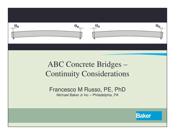
ABC Concrete Bridges – Continuity Considerations

Francesco M Russo, PE, PhD

Michael Baker Jr Inc – Philadelphia, PA

slide-2
SLIDE 2

Objective

  • Discuss the process for creating continuity in

ABC prestressed concrete bridges

slide-3
SLIDE 3

ABC Variations

  • “Ultra Fast” ABC
  • Closure times measured in hours
  • Prefabricated complete spans
  • “Really Fast” ABC
  • Closure time measured in days
  • Might use prefabricated elements or complete

modules

  • “Selective” ABC
  • Use of certain ABC elements to accomplish time

savings, i.e., decked bulb‐t superstructures

slide-4
SLIDE 4

Continuous Concrete Bridges And ABC

  • Basic premise ‐ Eliminate deck joints from the

bridge

  • Reduced joint installation and maintenance costs
  • Protection of beam ends and pier caps
  • Improved ride quality
slide-5
SLIDE 5

Design For Continuity

  • Three concepts
  • “Full Section” continuity
  • Possible to design for continuous behavior for

superimposed dead and live loads

  • “Deck Only” continuity
  • Only the deck is continuous
  • Spans behave as a series of simple spans
  • “No C.I.P. Deck” continuity
  • Continuous beam behavior without a c.i.p.

concrete deck

  • Each concept has unique design, construction

and ABC implications

slide-6
SLIDE 6

FULL SECTION CONTINUITY

Design and Construction Considerations

slide-7
SLIDE 7

Full Section Continuity

  • Requires girder ends to be embedded in a

common diaphragm

  • Requires connection for positive and negative

moments to be established

slide-8
SLIDE 8

Phase 1 – Girder / Span Placement

  • Erect pretensioned girders
  • For some ABC projects this might happen at

the “bridge farm”

  • Forms and rebar are installed for deck slab
slide-9
SLIDE 9

Phase 2 – Deck Placement / Span Assembly

  • For ABC projects with c.i.p. decks, cast slab on

erected girders in assembly areas

  • Leave slab blockout for eventual closure pour

and pier diaphragm

slide-10
SLIDE 10

Phase 3 – Establish Continuity

  • Form pier diaphragm and closure slab
  • Place diaphragm and slab reinforcing
  • Pour and cure the final closure
  • Complete railing closures
slide-11
SLIDE 11

Now What Happens?

  • Subsequent applied loads (railing, FWS, LL+I)

applied to a continuous system

  • Remaining creep and shrinkage potential of

the system must be resisted by the pier joints

  • Need to check joint effectiveness
  • Might still have to design as simple spans
slide-12
SLIDE 12

Restraint Moment Effects – AASHTO 5.14.1.4

slide-13
SLIDE 13

Restraint Moments – Calculation Options

  • Methods and theory date to the 1960’s
  • PCA Engineering Bulletin
  • “Design of Continuous Highway Bridges with

Precast, Prestressed Concrete Girders”

  • NCHRP Report 322
  • “Design of Precast Prestressed Bridge Girders

Made Continuous”

  • Software Programs
  • RMCALC from Washington DOT
slide-14
SLIDE 14

Age Effects - AASHTO 5.14.1.4.4

  • LRFD provides special exceptions if the

continuity is established at 90 days or later

  • Computation of restraint moments not

required

  • However…a positive moment connection is

still required

  • ABC implication – “old girders” can simplify

the design requirements for continuity joints

slide-15
SLIDE 15

JOINT DETAILS

slide-16
SLIDE 16

+M Connection With Extended Strands

slide-17
SLIDE 17

+M Connection With Bent Bars

slide-18
SLIDE 18
  • M Connection With Spliced Bars
  • Construction compromise
  • Engineers don’t like to splice bars in regions of high
  • stress. However, a Class C splice is the appropriate

solution

  • Large bars required for some connections. Double laps

can make this blockout large

  • ABC and traditional construction face the same issues

Lap Spliced Tension Bars

slide-19
SLIDE 19

Grouted Splice Sleeve Couplers

  • Unquowa Rd –

Fairfield, CT

slide-20
SLIDE 20

Mechanical Couplers

  • Used to splice up to #6 bars
  • Production rate – 600 per 2 man crew per shift
slide-21
SLIDE 21

Typical Fixed Pier Diaphragm Condition

  • Time consuming forming to conform to girder

and pier top shape

  • It’s not hard – it just takes a while
  • Does this interfere with the “A” of ABC?
  • What benefit will you derive from continuity?
slide-22
SLIDE 22

SAMPLE PROJECT

US89 over I‐15 – Utah DOT

slide-23
SLIDE 23

US89 over I-15 – Utah DOT

  • 2 Span – 290 ft. total length
  • SPMT span installation
  • Deck closure pours for continuity
slide-24
SLIDE 24

US89 over I-15 – Utah DOT

slide-25
SLIDE 25

Full Section Continuity Summary

  • Project conditions may impact the ability to

achieve continuity

  • Required speed of construction might

preclude the use of a c.i.p. closure pour. This is assumed to be rare however

  • Full section continuity requires a more

complicated forming and pouring operation

  • Might not be compatible with “ultra rapid”

ABC

  • Would be more compatible with a multi‐day

closure for ABC

slide-26
SLIDE 26

Full Section Continuity

  • Practical Considerations
  • Evaluate time of construction vs. structural

benefit

  • Continuity unlikely to materially affect the

design

  • i.e. wont change girder depth or number of beam

lines

  • So…in an ABC context is there really a benefit?
slide-27
SLIDE 27

DECK ONLY CONTINUITY

Design and Construction Considerations

slide-28
SLIDE 28

Deck Only Continuity

  • Only requires the deck to be made continuous for

“practical” reasons

  • i.e. reduced exposure of beam ends, ride quality
  • May have some ABC advantages over full continuity

due to simpler forming and reduced field pour volumes

slide-29
SLIDE 29

Link Slab Concept

slide-30
SLIDE 30

Link Slabs

  • Convenient option for establishing continuity

between discrete spans

  • Eliminates joints
  • Do NOT provide structural continuity
  • See…
  • Behavior and Design of Link Slabs for Jointless

Bridge Decks – Caner and Zia – PCI Journal May June 98

  • Field Demonstration of Durable Link Slabs…

Research Report RC1471 – Michigan DOT

slide-31
SLIDE 31

Link Slab Theory

  • Slab provides minimal continuity over center

supports

  • Applied loads produce end rotations
  • Slab is forced to bend / comply with the

induced curvatures

slide-32
SLIDE 32

Link Slab Theory

  • Zia study recommends 5% debonding

between slab and girder to allow for spread of cracking into a longer free length

slide-33
SLIDE 33

Link Slab Moments

  • where E, I are of the slab, θ is due to

imposed loads and L is the design length of the link slab

  • For L/800 deflection limit, θ = 0.00375 rad
slide-34
SLIDE 34

Design of Reinforcing

  • Design reinforcing using 40% Fy for imposed

moments

  • Space reinforcing for crack control
  • Limit crack width to 0.013” – use ϒe = 0.75 for

this condition

slide-35
SLIDE 35

Link Slab Guidance

  • Consider the effects of ALL sources of end

rotations

  • Superimposed loads producing downward

rotations

  • Governs top of slab tension steel
  • Possible camber growth
  • Governs bottom tension steel
  • Thermal gradients
  • Can affect either mat
slide-36
SLIDE 36

Some Additional Guidance

  • For instance….what if we are interested in

thermal loads / gradients

  • Rotations due to these effects can be

computed using the following procedure

  • ASCE Journal of Bridge Engineering March / April

2005

slide-37
SLIDE 37

MICHIGAN DOT AND U OF MI LINK SLAB STUDIES

slide-38
SLIDE 38

Link Slab Performance Considerations

  • Performance of traditional link slabs in

Michigan

  • Link slabs used to redeck / retrofit existing

multi‐span bridges to eliminate joints

  • Crack width of traditional link slabs was

generally good

  • Performance found to be linked to reinforcing

density and field execution

  • Some slabs with excessive crack width
  • Appear to be related to improper design and poor

construction practices

slide-39
SLIDE 39

Design and Field Demonstration of ECC Link Slabs for Jointless Bridge Decks Michael Lepech and Victor Li

  • Impose rotation corresponding to max span

deflection i.e. L/800

  • Use Engineered Cement Composites, a high

performance fiber reinforced concrete for its high tensile capacity and crack tolerance

slide-40
SLIDE 40

ECC Link Slab Features

  • Use fiber reinforced and high tensile strength

HPC to create more durable link slabs

  • Reinforcing density much lower than

traditional link slabs

  • Early mixes shown to be shrinkage crack

prone and susceptible to high skew

  • Refined mix designs and 25° skew limit

recommended

  • 7 day wet cure required – ABC implication
slide-41
SLIDE 41

I-84 OVER UPRR – REDECKING PROJECT

Innovative use of full depth precast decks in a link slab concept

slide-42
SLIDE 42

I-84 over UPRR – Taggart, UT

  • ABC redecking

project

  • Existing multi‐

span PC beam bridge

slide-43
SLIDE 43

I-84 over UPRR

  • 3 Span Simple Span Bridge w/ Joint Seals
  • 85 ft., 78 ft., 75 ft.
  • Project converted to 3‐span jointless
slide-44
SLIDE 44

Full Width Panel – Continuous Over Skewed Joint

slide-45
SLIDE 45

Panel P4C

slide-46
SLIDE 46

Transverse Joint Details

slide-47
SLIDE 47

Keyway Details

slide-48
SLIDE 48

“NO C.I.P. DECK” CONTINUITY

slide-49
SLIDE 49

No C.I.P. Deck Continuity Concept

  • Attain continuous structural behavior for

bridges without a c.i.p. or precast deck

  • Challenge
  • How to establish the –M continuity
slide-50
SLIDE 50

O’MALLEY ROAD – ALASKA DOT

slide-51
SLIDE 51

Typical Section

  • ABC Concept – Decked Bulb T
  • 2 Spans – 110 ft. each
slide-52
SLIDE 52

Pier Diaphragm

  • Extended strands for +M connection
  • Hooked flange bars for –M connection

3 ft. closure pour

slide-53
SLIDE 53

SIBLEY POND - MAINE

slide-54
SLIDE 54

Typical Section

  • Series of 79 ft. spans made continuous for LL
  • Next Type D sections chosen for ABC
  • ABC challenge – achieving continuity without a

c.i.p. concrete deck

slide-55
SLIDE 55

Longitudinal Continuity

  • Bottom bars hooked into diaphragm
  • Top bars spliced with couplers
  • Small gap would not allow lap splices
  • HPC closure pour
slide-56
SLIDE 56

CONCLUSIONS AND OBSERVATIONS

slide-57
SLIDE 57

Conclusions & Observations

  • Continuity can be achieved by
  • Full section continuity
  • Deck only continuity
  • No‐Deck continuity
  • Continuity details for ABC borrow many

elements from conventional construction

slide-58
SLIDE 58

Some Things to Consider

  • May require special high early strength

closure materials

  • This is only a small part of complete ABC

solutions

  • Other activities such as railing completion still

required

  • Maybe this takes the continuity connection
  • ff the critical path anyway ?
slide-59
SLIDE 59

Some Thoughts

  • ABC can take a long time – just somewhere else
  • Once you get to the site everything needs to be

simple, predictable and achievable

  • Make the field work as simple as possible
  • Construct forms in advance
  • Pour as little concrete as possible
  • Simplify the operations
  • Durability can not be sacrificed in the name of

speed or we will just be out there doing it again

slide-60
SLIDE 60

Potential New Solutions

  • Could consider a precast link slab like the

UDOT Taggart project to eliminate a c.i.p. closure

slide-61
SLIDE 61

Acknowledgements

  • Thanks to many who provided information
  • Mary Lou Ralls
  • Reid Castrodale
  • William Nickas
  • Mike Culmo
  • Utah DOT
  • My colleagues at Michael Baker
  • The time is yours….