(A final note on) Mobile Kinematics Manipulator Kinematics 3 4 - - PDF document

a final note on mobile kinematics manipulator kinematics
SMART_READER_LITE
LIVE PREVIEW

(A final note on) Mobile Kinematics Manipulator Kinematics 3 4 - - PDF document

4/2/20 (A final note on) Mobile Kinematics Kinematics: overview, 2 transforms, and wheels Given this setup: P P x z I = y y P y 1 1 P x x 1 1 x We can map { X I ,Y I } (global) { X R ,Y R } (robot) y


slide-1
SLIDE 1

4/2/20 1

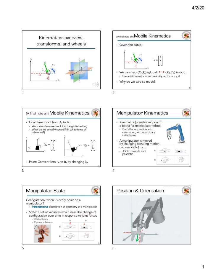
Kinematics: overview, transforms, and wheels

x1 y1 P

θ

x1 y1 P

θ y z x

1

2 2

§ Given this setup: § We can map {XI ,YI} (global) ßà {XR ,YR} (robot)

§ Use rotation matrices and velocity vector in x, y, θ

§ Why do we care so much?

(A final note on) Mobile Kinematics

x

1

y

1

P

θ

x1 y1 P

θ

ξI = x y θ

2

3 3

§ Goal: take robot from AI to BI

§ We know where we want it in the global setting § What do we actually control? (In what frame of

reference?)

§ Point: Convert from AI to BI by changing ξR

(A final note on) Mobile Kinematics

YR XR YI XI θ P YR XR θ YI XI

ξA = x y θ ξB = x’ y’ θ’

3

4 4

§ Kinematics (possible motion of

a body) for manipulator robots

§ End effector position and

  • rientation, wrt. an arbitrary

initial frame

§ A manipulator is moved

by changing (sending motion commands to) its…

§ Joints: revolute and

prismatic

Manipulator Kinematics

4

5 5

Configuration: where is every point on a manipulator?

§ In

Instantaneous description of geometry of a manipulator

§ State: a set of variables which describe change of

configuration over time in response to joint forces

§

Control inputs

§

External influences

Manipulator State

P R

θ d

5

6 6

Position & Orientation

Images from: dreamstime.com

6

slide-2
SLIDE 2

4/2/20 2

7 7

Position & Orientation

Images from: dreamstime.com

7

8 8

Forward Kinematics & IK

Images from: dreamstime.com

8

9 9

§ Description: how

many parameters…

§ …to describe planar

position & orientation?

§ …to describe 3D

position & orientation?

§ In 3D, it’s always 6

§ Where is it on x, y, z? § What is its x, y, z

rotation?

Mobile vs. Manipulator

x

1

y

1

P

θ

x1 y1 P

θ

ξI = x y θ

9

10 10

§ The st

state sp space is the set of all possible states

§ The st

state of the manipulator is:

§ A set of variables which describe changes in

co configuration over time, in response to joint forces + external forces

§ Where do joint forces come from?

§ Controllers!

§ So, given some set of joints,

what signals do we send?

§ In jo

join int t space vs. Ca Cartesian space

Kinematics Problem

Images from: dreamstime.com

10

11 11

§ Joint space: we co

cont ntrol the robot’s DoFs

§ So we issue commands in terms of those § Mobile: “Roll forward 2 meters, rotate 53˚ clockwise” § Manipulator: “Rotate joint two 90˚ and joint four 65˚,

then slide joint three 17cm”

§ Cartesian space: usually we wa

want to accomplish things in terms of the world

§ Mobile: Go to the building in B2 § Manipulator: get the object on the

table in front of you

§ Kinematics lets us tra

transform back and forth

Joint vs. Cartesian space

11

12 12

But wait, there’s more…

§ Goal: take robot end effector from AI to BI

§ We know where we want it in the global setting § What do we actually control?

§ Point: Convert from AI to BI § Now a 6 ßà 6 transformation

Goal

A B

Images from: dreamstime.com

12

slide-3
SLIDE 3

4/2/20 3

13 13 § We derived this geometrically :

§

If we assume frame axes are of length 1

§

a = cos θ

§

b = sin θ

§

c = -sin θ

§

d = cos θ

§

Rotations around z à 0s and 1s

Review: Z Rotation Matrix*

R θ

( ) =

cosθ −sinθ sinθ cosθ 1 ⎡ ⎣ ⎢ ⎢ ⎢ ⎤ ⎦ ⎥ ⎥ ⎥

yI xI a b θ yR d c xR * AKA orthogonal rotation matrix

13

14 14 § In practice, it’s really this: § Rotations around z à 0s and 1s

Review: Z Rotation Matrix*

R θ

( ) =

cosθ −sinθ sinθ cosθ 1 ⎡ ⎣ ⎢ ⎢ ⎢ ⎤ ⎦ ⎥ ⎥ ⎥

* AKA orthogonal rotation matrix yI xI yR xR zI zR

14

15 15

§ Similarly derived

from axis of rotation and trigonometric values of projections

Other Rotation Matrices

𝑆" = 1 𝑑𝑝𝑡𝜄" −𝑡𝑗𝑜𝜄" 𝑡𝑗𝑜𝜄" 𝑑𝑝𝑡𝜄" 𝑆- = 𝑑𝑝𝑡𝜄- 𝑡𝑗𝑜𝜄- 1 −𝑡𝑗𝑜𝜄- 𝑑𝑝𝑡𝜄- 𝑆. = 𝑑𝑝𝑡𝜄. −𝑡𝑗𝑜𝜄. 𝑡𝑗𝑜𝜄. 𝑑𝑝𝑡𝜄. 1

15

16 16

§ What if we don’t just rotate around a single axis? § Any rotation in 3D space

can be broken down into single-axis rotations

§ Given orthogonal axes

§ Multiply rotation matrices: § Can do any number of rotations; just multiply out

Complex Rotations

zI xI zR xR yI yR

R = 1 𝑑𝑝𝑡𝜄" −𝑡𝑗𝑜𝜄" 𝑡𝑗𝑜𝜄" 𝑑𝑝𝑡𝜄" 𝑑𝑝𝑡𝜄- 𝑡𝑗𝑜𝜄- 1 −𝑡𝑗𝑜𝜄- 𝑑𝑝𝑡𝜄-

16

17 17

§ Add a number of chained frames of reference

Mobile to Manipulator

x1 y1 P θ x1 y1 P θ

17

18 18

Multiframe Kinematics

§ Ho

How w many frames of reference do we have?

§ We’ve been translating among frames based on

possible motion

§ How do they re

relate?

18

slide-4
SLIDE 4

4/2/20 4

19 19

Kinematic Chaining

§ Do you need to do every transformation? § What do we really care about?

19

20 20

joint i joint i-1 joint i+1 § Arm made up of links in a chain § Joints each have <x,y,z> and roll/pitch/yaw

§ So, ea

each h joint nt has a coordinate system

§ We label links, joints, and angles

Describing A Manipulator

20

21 21

Forward Kinematics

§ Vector Φ represents the array of M joint values: § Vector e represents an array of N values that describe

the end effector in world space:

§ If we need end effector position and orientation, e

would contain 6 DOFs: 3 translations and 3 rotations. If we only need end effector position, e would just contain the 3 translations.

[ ]

M

f f f ...

2 1

= Φ e = e1 e2 ... eN ⎡ ⎣ ⎤ ⎦

21

22 22

§ Forward:

§ Inputs: joint angles § Outputs: coordinates of end-effector

§ Inverse:

§ Inputs: desired coordinates of end-

effector

§ Outputs: joint angles

§ Inverse kinematics are tricky

§ Multiple solutions § No solutions § Dead spots

Forward & Inverse

Joint space (robot space – previously R) θ1, θ2, …, θn Cartesian space (global space – previously I) {x,y,z}, r/p/y

22

23 23

joint i joint i-1 joint i+1

§ Arm made up of links in a chain

§ How to describe each link? § Many choices exist

§

DH parameters, quaternions are widely used, Euler angles… § Joints each have coordinate system

§ {x,y,z}, r/p/y

Describing A Manipulator

23

24 24

§ We are we looking for transformation matrix

T, going from frame i to frame i-1:

§ Determine position and orientation of end-

effector as function of displacements in joints

§ Why?

§ So we can multiply out along all joints

Forward: i à i-1

(also written

T or i-1Ti )

i i-1

T i

i-1

24

slide-5
SLIDE 5

4/2/20 5

25 25

joint i joint i-1 joint i+1

Forward Kinematics and IK

§ Joint angles ⇆ end effector configuration § Can string together rotations with multiplication

§ So, can get end effector rotation by

§ Finding rotation from

[joint i-1 to i] ✕ [joint i to i+1] ✕ …

§ Rot

Rotat ation

  • n of
  • f end

ef effect ector frame, relative to bas base fr frame

www.youtube.com/watch?v=lVjFhNv2N8o

25

26 26

Matrices for Pure Translation

ξI = xI yI zI θ ξR = xR yR zR θ Origin point of R in I: 3 1 In 3D: 1 0 0 0 0 1 0 3 0 0 1 0 0 0 0 1 Generally: 1 0 0 x 0 1 0 y 0 0 1 z 0 0 0 1

26

27 27

Matrices for Pure Rotation

ξI = x y z θI ξR = x y z θR Around z: Review? Introduction to Homogeneous Transformations & Robot Kinematics Jennifer Kay 2005

ce.aut.ac.ir/~shiry/lecture/robotics/amr/kinematics.pdf

27

28 28

Describing A Manipulator

joint i joint i-1 joint i+1

§ Arm made up of links in a chain

§ How to describe each link? § Many choices exist § DH parameters widely used

§

Although it’s not true that quaternions are not widely used § DH parameters

§ Denavit-Hartenberg § ai-1, αi-1, di, θ2

28

29 29

§ Efficient way to find transformation matrices 1.

Set frames for all joints

§ This is actually the tricky part.

2.

Calculate all DH parameters from frames

§

4 DH parameters fully define position and orientation (not 6)

3.

Populate DH parameter table

4.

Populate joint-to-joint DH transformation matrices

§

Matrix for 0-1, matrix for 1-2, etc.

5.

Multiply all matrices together, in order

§

0-1 × 1-2 × 2-3 × …

Denavit-Hartenberg Method

29

30 30

P § What’s the frame of reference for a joint?

§ Actually, completely flexible

§ We usually choose:

§ 1 axis through the center of

rotation/direction of displacement

§ 2 more perpendicular to that

§

Which can be any orientation! § We can move the origin

§ P is no longer <0, 0, 0>

§ To use DH method, choose frames carefully

Defining Frames for Joints

30

slide-6
SLIDE 6

4/2/20 6

31 31

§ z axis must be axis of motion

§ Rotation around z for revolute § Translation along z for prismatic

§ xi axis orthogonal to zi an

and zi-1

§ There’s always a line that satisfies this

§ y axis must follow the right-hand rule

§ Fingers point +x § Thumb points +z § Palm faces +y

§ xi axis must intersect zi-1 axis (may mean translating

  • rigin)

Choosing Frames for DH

+x +z +y

31

32 32

ai-1 : link length – distance Zi-1 and Zi along Xi αi-1 : link twist – angle Zi-1 and Zi around Xi di : link offset – distance Xi-1 to Xi along Zi θi : joint angle – angle Xi-1 and Xi around Zi

Find DH Parameters

§ Fewer values to represent same info § Efficient to calculate

32

33 33

§ A way of finding transformation matrix (quickly) 1.

Assign DH frames to DoFs (previous slide)

§

This takes practice.

2.

Create a parameter table

§ Rows = (# frames – 1) § Columns = 4

4 (always) ß your DH parameters θ, α, a, d

Denavit-Hartenberg Method

θ α a d frame 0-1 θ0-1 α0-1 a0-1 d0-1 frame 1-2 θ1-2 α1-2 a1-2 d1-2 frame 2-3 … … … …

33

34 34

§ Given parameter table, 3.

Fill out transformation matrix* for each transition:

3.

And multiply. Ex:

§

is the same matrix as would be found by

  • ther methods. DH is fast and efficient.

Denavit-Hartenberg Method

R2

Ri

i−1 =

cosθi −sinθi cosαi,i+1 sinθi sinαi,i+1 ai,i+1cosθi sinθi cosθi cosαi,i+1 −cosθi sinαi,i+1 ai,i+1sinθi sinαi,i+1 cosαi,i+1 di 1 ⎡ ⎣ ⎢ ⎢ ⎢ ⎢ ⎢ ⎤ ⎦ ⎥ ⎥ ⎥ ⎥ ⎥

R2

0 = R 1 0R2 1

34

35 35

Example: Rotation in Plane

35

36 36

ai-1 : di distan ance Zi-1 an and d Zi al alon

  • ng

g Xi αi-1 : an angl gle Zi-1 an and d Zi ar arou

  • und

d Xi di : di distan ance Xi-1 to to Xi al alon

  • ng

g Zi θ2 : an angl gle Xi-1 an and d Xi ar arou

  • und

d Zi

§ Coordinate transformation:

Transformation i to i-1

together: screw displacement together: screw displacement

36

slide-7
SLIDE 7

4/2/20 7

37 37

Transformation i to i-1

Transformation in DH:

37