
SLIDE 1
OM0162 12
5.0 Installation Instructions
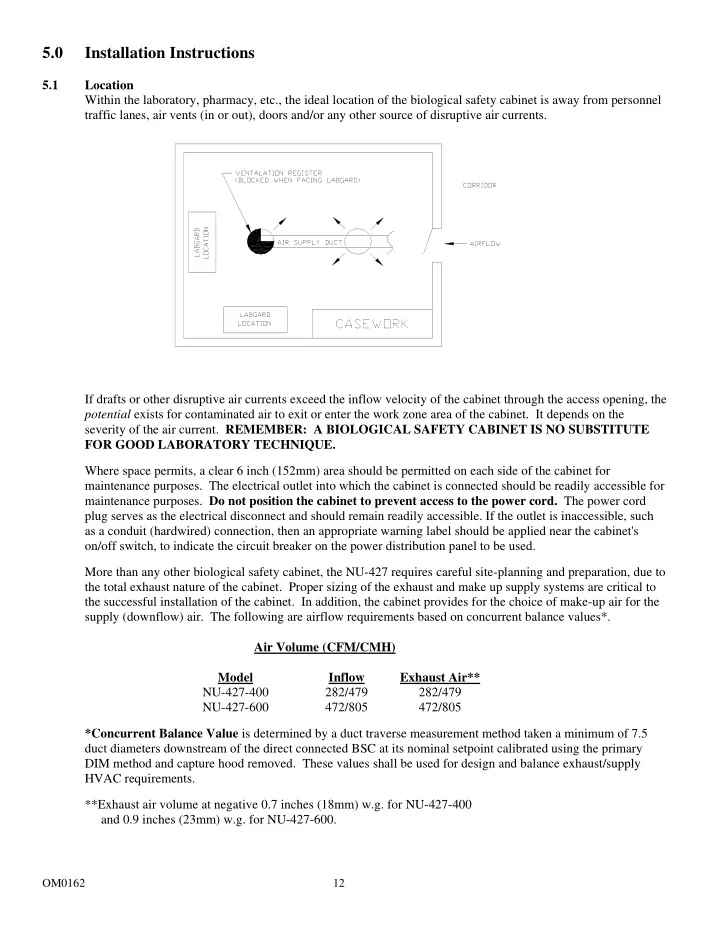
5.1 Location Within the laboratory, pharmacy, etc., the ideal location of the biological safety cabinet is away from personnel traffic lanes, air vents (in or out), doors and/or any other source of disruptive air currents. If drafts or other disruptive air currents exceed the inflow velocity of the cabinet through the access opening, the potential exists for contaminated air to exit or enter the work zone area of the cabinet. It depends on the severity of the air current. REMEMBER: A BIOLOGICAL SAFETY CABINET IS NO SUBSTITUTE FOR GOOD LABORATORY TECHNIQUE. Where space permits, a clear 6 inch (152mm) area should be permitted on each side of the cabinet for maintenance purposes. The electrical outlet into which the cabinet is connected should be readily accessible for maintenance purposes. Do not position the cabinet to prevent access to the power cord. The power cord plug serves as the electrical disconnect and should remain readily accessible. If the outlet is inaccessible, such as a conduit (hardwired) connection, then an appropriate warning label should be applied near the cabinet's
- n/off switch, to indicate the circuit breaker on the power distribution panel to be used.