
SLIDE 1
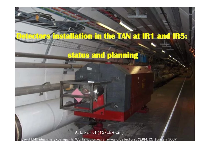
Detectors installation in the TAN at IR1 and IR5: Detectors installation in the TAN at IR1 and IR5: Detectors installation in the TAN at IR1 and IR5: Detectors installation in the TAN at IR1 and IR5: status and planning status and planning status and planning status and planning
- A. L. Perrot (TS/LEA-Int)
Joint LHC Machine Experiments Workshop on very forward detectors, CERN, 25 January 2007