
SLIDE 1
www.inter
- fab.com
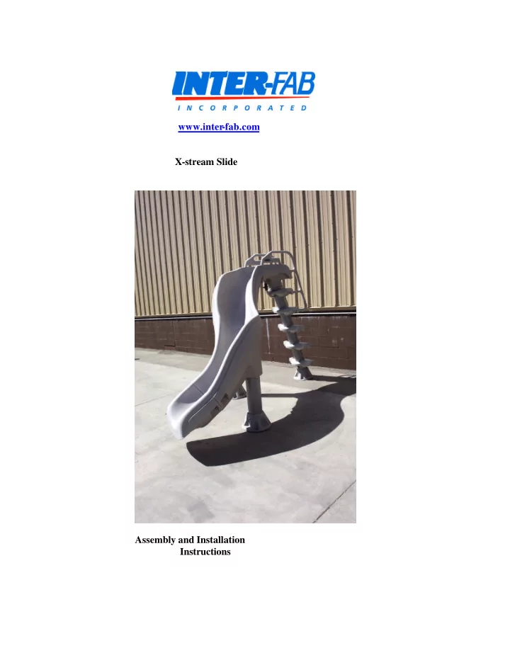
www.inter -fab.com X-stream Slide Assembly and Installation - - PDF document
www.inter -fab.com X-stream Slide Assembly and Installation Instructions Assembly/Installation Instructions for X-stream Slide The following Assembly and Installation instructions are listed in the correct sequence for a straightforward