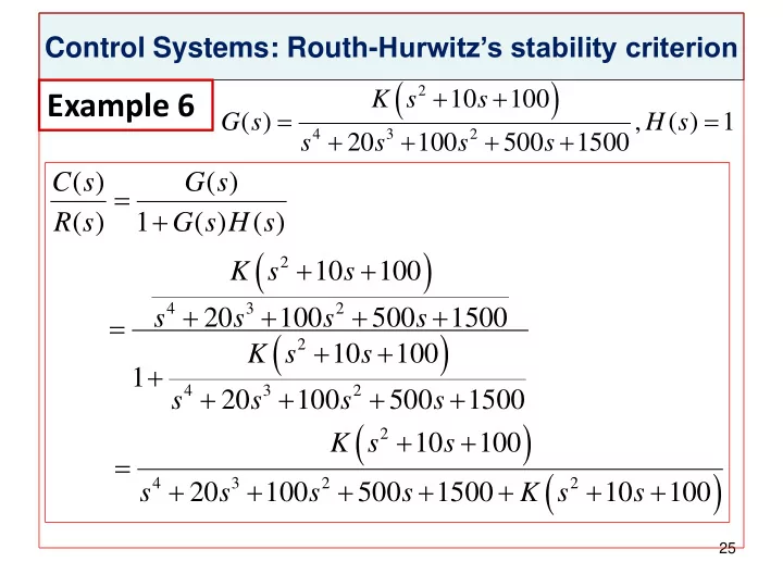
2 k s 10 s 100 4 3 2 s 20 s 100 s 500 s 1500
play

2 K s 10 s 100 4 3 2 s 20 s 100 s 500 s - PowerPoint PPT Presentation

Control Systems: Routh- Hurwitzs stability criterion 2 K s 10 s 100 Example 6 G s ( ) , H s ( ) 1 4 3 2 20 100 500 1500 s s s s C s ( ) G s ( ) R s ( ) 1 G


  1. Control Systems: Routh- Hurwitz’s stability criterion     2 K s 10 s 100 Example 6   G s ( ) , H s ( ) 1     4 3 2 20 100 500 1500 s s s s C s ( ) G s ( )   R s ( ) 1 G s H s ( ) ( )     2 K s 10 s 100     4 3 2 s 20 s 100 s 500 s 1500      2 K s 10 s 100  1     4 3 2 s 20 s 100 s 500 s 1500     2 K s 10 s 100           4 3 2 2 20 100 500 1500 10 100 s s s s K s s 25

  2. Control Systems: Routh- Hurwitz’s stability criterion Example 6 Method I using determinants         4 3 2 B s ( ) s 20 s s (100 K ) s (500 10 ) 1500 100 K K  a a 0 20 500 10 K 0 3 1      a a a 1 100 K 1500 100 K 3 4 2 0  0 a a 0 20 500 10 K 3 1 The value of ∆ 1 =20 >0 and the value of ∆ 2 =1500+10K >0 ,     100( K 7.8)( K 192.2) 7.8 < K < 192.2 conditions for 3 stability 26

  3. Control Systems: Routh- Hurwitz’s stability criterion Example 6 Method II using array         4 3 2 B s ( ) s 20 s s (100 K ) s (500 10 ) 1500 100 K K n s a a a 4 2 0  1 n 0 s a a 3 1  a a a a a a     n 2 3 2 4 1 3 o s b b 0 3 0 a a 3 3 b a b a   n 3 3 1 0 3 s b 3 27

  4. Control Systems: Routh- Hurwitz’s stability criterion Example 6 Method II using array   n s 1 100 K 1500 100 K   n 1 s 20 500 10 K 0  1500 10 K   n 2 s 1500 100 K 0 20   100( K 7.8)( K 192.2)  n 3 s  1500 10 K conditions for 7.8 < K < 192.2 stability 28

  5. Control Systems: Routh- Hurwitz’s stability criterion Example 7 K   ( ) , ( ) 1 G s H s    4 3 2 s s s s C s ( ) G s ( )   ( ) 1 ( ) ( ) R s G s H s K    4 3 2 s s s s       4 3 2 B s ( ) s s s s K K  1    4 3 2 s s s s K      4 3 2 s s s s K 29

  6. Control Systems: Routh- Hurwitz’s stability criterion Example 7 Method I using determinants 1 1 0   1 1 K 3 ∆ 1 =1 >0 and the value of ∆ 2 =0. ∆ 3 =-K 0 1 1 The system is unstable for all values of K 30

  7. Control Systems: Routh- Hurwitz’s stability criterion Example 7 Method II using array      4 3 2 B s ( ) s s s s K n s a a a 4 2 0  n 1 s a a 0 3 1  a a a a a a    n 2 3 2 4 1 3 o s b b 0 3 0 a a 3 3 b a b a   n 3 3 1 0 3 s b 3 31

  8. Control Systems: Routh- Hurwitz’s stability criterion Example 7 Method II using array 4 s 1 1 K 3 s 1 1 0  2 The system is unstable for all values 0 s K of K K  1 s 1 0 0  0 s K 0 0 32

  9. ME 779 Control Systems Topic #14 Controller Basics Reference textbook : Control Systems, Dhanesh N. Manik, Cengage Publishing, 2012 1

  10. Control Systems: Controller Basics Learning Objectives • Proportional controllers • Proportional and derivative controllers • Proportional and integral controllers • Proportional, integral and derivative controllers 2

  11. Control Systems: Controller Basics Closed-loop (feedback) systems Block diagram 3

  12. Control Systems: Controller Basics Proportional controller for inertia load Proportional controller Proportional control system for inertia load 4

  13. Control Systems: Controller Basics Proportional controller for inertia load K p K K Closed-loop response C s ( ) 2 Js    p p    2 2 2 K R s ( ) Js K J s ( )  p p n 1 2 Js K   p n J    c t ( ) 1 cos t Step response n 5

  14. Control Systems: Controller Basics Proportional controller for inertia load Step response 6

  15. Control Systems: Controller Basics Proportional plus derivative controller for inertia load Proportional plus derivative controller K  d T d K p Proportional and derivative control for inertial load 7

  16. Control Systems: Controller Basics Proportional plus derivative controller for inertia load  K (1 T s )   p d ( ) (1 ) G s K T s  K (1 T s ) ( ) C s 2 c p d Js   p d    (1 ) 2 K T s R s ( ) Js K (1 T s )  p d p d 1 2 K K Js T   p   d p  K (1 T s ) 2 J n  p d J   K T K   p d p 2   J s s   J J        K          p  t  ( ) 1 cos sin c t e t t n  d d 2     J   2  1    n Step response       K T 1       p d t 2   e sin 1 t n  n   J  2    1 n 8

  17. Control Systems: Controller Basics Proportional plus derivative controller for inertia load  K (1 T s ) p d  C s ( ) 2 Js cs   K (1 T s ) ( ) R s  p d 1  2 Js cs  K (1 T s )  p d    2 Js s c ( K T ) K      p d p c K T 1   p d   2   JK    p K (1 T s ) C s ( )  p d     2 2 R s ( ) J s ( 2 s ) n n 9

  18. Control Systems: Controller Basics Proportional plus derivative controller for inertia load        K          p t   c t ( ) 1 e cos t sin t n  d d 2     Step response J  2   1    n       K T 1       p d t 2   e sin 1 t n  n   J  2   1  n Derivative control adds K    p c ( ) 1 damping to the system J  2 n 10

  19. Control Systems: Controller Basics Comparison of proportional and integral controllers Integral Proportional K K  i  G p G  2  1 s s ( 1) s 1  E s ( ) 1 s 1  E s ( ) 1 1 s s ( 1)      1 2      K 2 R s ( ) 1 G s ( ) s 2 R s ( ) 1 G s ( ) s s 1  i 1 2 1  s s ( 1) 11

  20. Control Systems: Controller Basics Comparison of proportional and integral controllers Integral Proportional   E s ( ) 1 1 s s ( 1) E s ( ) 1 s 1      2 1    K 2 R s ( ) 1 G s ( ) s s 1    i R s ( ) 1 G s ( ) s 2 1 2  1 s s ( 1)   K ( s 1) U s ( ) K s ( 1) U ( ) s   p 2 1 i    2 R s ( ) s s 1 R s ( ) ( s 2) C s ( ) 1 1 C s 1 ( ) 1 1     2        2 2 R s ( ) s s K s s 1 R s ( ) s 1 K s 2 i p 12

  21. Control Systems: Controller Basics Comparison of proportional and integral controllers Step response Integral Proportional     3 1 3 e     1 0.5 t   2 t e t ( ) e cos t sin t     e t ( ) 1 2 2 2   3 1 2     e  1   2 t   1 3 3 u t ( ) 1     0.5 t   u t ( ) 1 e sin t cos t 1 2 2   2 2   3   e    1   2 t 1 3 3       c t ( ) 1 0.5 t   c t ( ) 1 e sin t cos t 1 2   2 2 2   3 13

  22. Control Systems: Controller Basics Comparison of proportional and integral controllers Steady-state error for step input 14

  23. Control Systems: Controller Basics Comparison of proportional and integral controllers Plant input for step input 15

  24. Control Systems: Controller Basics Comparison of proportional and integral controllers Closed-loop response for step input 16

  25. Control Systems: Controller Basics PI (proportional-integral) controllers 17

  26. Control Systems: Controller Basics PI (proportional-integral) controllers     sK K K 1    p i i     G K   p     1 ( 1) s s s s  E s ( ) 1 s s ( 1)       2 R s ( ) 1 G s ( ) s s (1 K ) K 1 p i   ( s 1)( sK K ) U ( ) s   p i 1    2 R s ( ) s s (1 K ) K p i 18

  27. Control Systems: Controller Basics PI (proportional-integral) controllers  ( sK K ) C s ( ) 1   p i     2 ( ) (1 ) ( 1) R s s s K K s p i u t  e   t ( ) 1 e t ( ) Step response   e  t   c t ( ) 1 19

  28. Control Systems: Controller Basics PI (proportional-integral) controllers Steady-state error for step input 20

  29. Control Systems: Controller Basics PI (proportional-integral) controllers Plant input for step input 21

  30. Control Systems: Controller Basics PI (proportional-integral) controllers Closed-loop response for step input Integral control reduces steady- state error 22

Download Presentation
Download Policy: The content available on the website is offered to you 'AS IS' for your personal information and use only. It cannot be commercialized, licensed, or distributed on other websites without prior consent from the author. To download a presentation, simply click this link. If you encounter any difficulties during the download process, it's possible that the publisher has removed the file from their server.

Recommend


More recommend