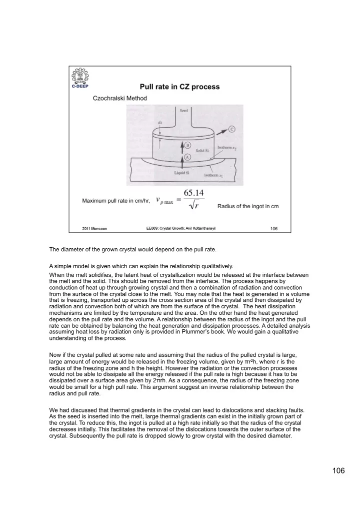
SLIDE 1 The diameter of the grown crystal would depend on the pull rate. A simple model is given which can explain the relationship qualitatively. When the melt solidifies, the latent heat of crystallization would be released at the interface between the melt and the solid. This should be removed from the interface. The process happens by conduction of heat up through growing crystal and then a combination of radiation and convection from the surface of the crystal close to the melt. You may note that the heat is generated in a volume that is freezing, transported up across the cross section area of the crystal and then dissipated by radiation and convection both of which are from the surface of the crystal. The heat dissipation mechanisms are limited by the temperature and the area. On the other hand the heat generated depends on the pull rate and the volume. A relationship between the radius of the ingot and the pull rate can be obtained by balancing the heat generation and dissipation processes. A detailed analysis assuming heat loss by radiation only is provided in Plummer’s book. We would gain a qualitative understanding of the process. Now if the crystal pulled at some rate and assuming that the radius of the pulled crystal is large, large amount of energy would be released in the freezing volume, given by πr2h, where r is the radius of the freezing zone and h the height. However the radiation or the convection processes would not be able to dissipate all the energy released if the pull rate is high because it has to be dissipated over a surface area given by 2πrh. As a consequence, the radius of the freezing zone would be small for a high pull rate. This argument suggest an inverse relationship between the radius and pull rate. We had discussed that thermal gradients in the crystal can lead to dislocations and stacking faults. As the seed is inserted into the melt, large thermal gradients can exist in the initially grown part of the crystal. To reduce this, the ingot is pulled at a high rate initially so that the radius of the crystal decreases initially. This facilitates the removal of the dislocations towards the outer surface of the
- crystal. Subsequently the pull rate is dropped slowly to grow crystal with the desired diameter.
106
SLIDE 2
Usually this is true at any material interface. The solubility of impurities would be different in the two materials on either sides of the interface leading to segregation. We will consider this again when we discuss oxidation. The segregation coefficient has to be defined a particular interface. In this module, the segregation coefficient is defined between the solid crystal and the melt. Usually K < 1 because most of the dopants and impurities of interest have higher solubility in the liquid phase than in the solid phase.
107
SLIDE 3
Segregation coefficient of most of the impurities is less than 1, i.e. only a fraction of dopants from the liquid would be incorporated in the freezing material. Suppose we start with a fixed concentration of the dopant in the melt. Usually this is achieved by adding powders of heavily doped Si with the desired dopant into the Si charge. As the crystal grows, dopants would be incorporated at a lower concentration than in the melt. As a consequence, the concentration of the dopants in the melt would increase with time. Consequently the dopant concentration in the growing film would increase with time and hence along the length of the ingot. If K = 1, the dopant concentration in the ingot would follow the distribution in the melt. It can be appreciated that it would be easier to obtain a rather uniform doping of Boron along the ingot as the K is close to 1. On the other hand Al can be expected to show a sharp increase in concentration as the ingot grows. Concentration of Au would also increase along the ingot length. It can be anticipated that the life time of minority carriers would decrease along the length of the ingot. So if someone gives you the life time of minority carriers on a wafer, it is important to ask the basis of the statement. Different wafers from the same ingot would not have the same minority carrier lifetime.
108
SLIDE 4
We want to find out CS as a function of the length of the ingot. CM and WM are known and W can be measured. S, CL and CS would change as the crystal grows. All of them would increase with time.
109
SLIDE 5
WM – W is the weight of the melt at the point of time we are considering. Equation (3) is obtained by solving (2) for CS and substituting in (1). WMCM is the initial weight of the dopant in the melt.
110
SLIDE 6
Using the values of K for the various dopants on a previous slide, generate the plots for CS/CM versus the fraction of the melt solidified for B, As, P, Al and Au in Si.
111
SLIDE 7 Solid solution hardening is similar to the strengthening of iron by the addition of carbon to make steel, or addition of Cu to Au for jewelry making. Pure Au is a soft
- material. The additive is supposed to prevent the propagation of defects through the
composite.
112
SLIDE 8
The reason for precipitation in CZ wafers is easy to understand. In fact precipitation technologies are desired for moving the oxygen to non device regions of the wafer. If a wafer that has not been subjected to a precipitation process is treated at high process temperatures, precipitation is unlikely as the SiO2 formed would dissociate. Precipitation process has to be carried out at a temperature at which the SiO2 precipitates but the temperature is not high so that it dissociates. Once sufficiently large nucleates of SiO2 are formed (> 1nm), temperature can be increased and the nuclei of SiO2 is seen to grow.
113
SLIDE 9 In the previous slide we had seen that vacancies and intersticials play an important role in precipitation. It is possible to do the precipitation processes under conditions
- r on wafers preconditioned for vacancy creation. Examples include: RTP, ion
implantation created damages on the backside of the wafer etc. For modern VLSI applications, devices are made on epitaxially grown Si layers on top of CZ wafers which are free from such defects. So in such cases, intentional precipitation may not be necessary. The defects can be seen in SEM or if large enough (>1um) even using optical
- microscopes. For enhancing the contrast, the defects can be etched. For example
an HF treatment can etch the SiO2 precipitates selective to Si. Such a process is called defect delineation or decoration.
114
SLIDE 10
Carbon and SiO2 precipitates are some times seen near to each other due to the different kinds of stresses created by them in the crystals. When they are nearby, the total stress generated would be low.
115
SLIDE 11 The float zone (FZ) process for crystal growth and purification is shown in the
- figure. The starting material is the electronic grade poly-Si rods made by CVD
processes discussed earlier. The rode is clamped to a seed crystal and the whole assembly is fixed to a support with the seed contacting the support. A coil type electrode is placed around the rod and an appropriate RF power is supplied to the
- electrode. The magnetic fields generated by the RF coil would produce eddy
currents in the conducting Si rod. This has two consequences: The rod would melt due to heating (I2R, R being the resistance of the material), and the current in the rod in turn would generate a magnetic field. The interaction between the two magnetic fields would keep the poly-Si above the melt levitating. The length of the molten zone is called the zone length, L. The crystal would grow from the bottom. The coil would be slowly moved upwards and crystallization would proceed from bottom up.
116
SLIDE 12
Due to this reason it is difficult to uniformly dope the crystal by doping the initial rode.
117
SLIDE 13
Refer to S. K. Gandhi for the analysis.
118
SLIDE 14
119