
SLIDE 1
1
Mesh Network Cross Layer Design : Seminar 3
Jonas Karlsson Karlstad Universitet
Email: jonas.karlsson@kau.se
Topics in Computer Networks 2010
Slides adopted from ”Cross-layer Air Interface Design for Wireless Systems” - Dr. Giovanni Giambene, “Cross Layer Overview” - Murad Khalid and “Cross-Layer Design in Wireless Networks” - Philipp Hurni
Summary Summary
Introduction, What is CrossLayer Design ? Taxonomy of cross-layer methods Detailed overview on cross-layer
interactions
Introduction
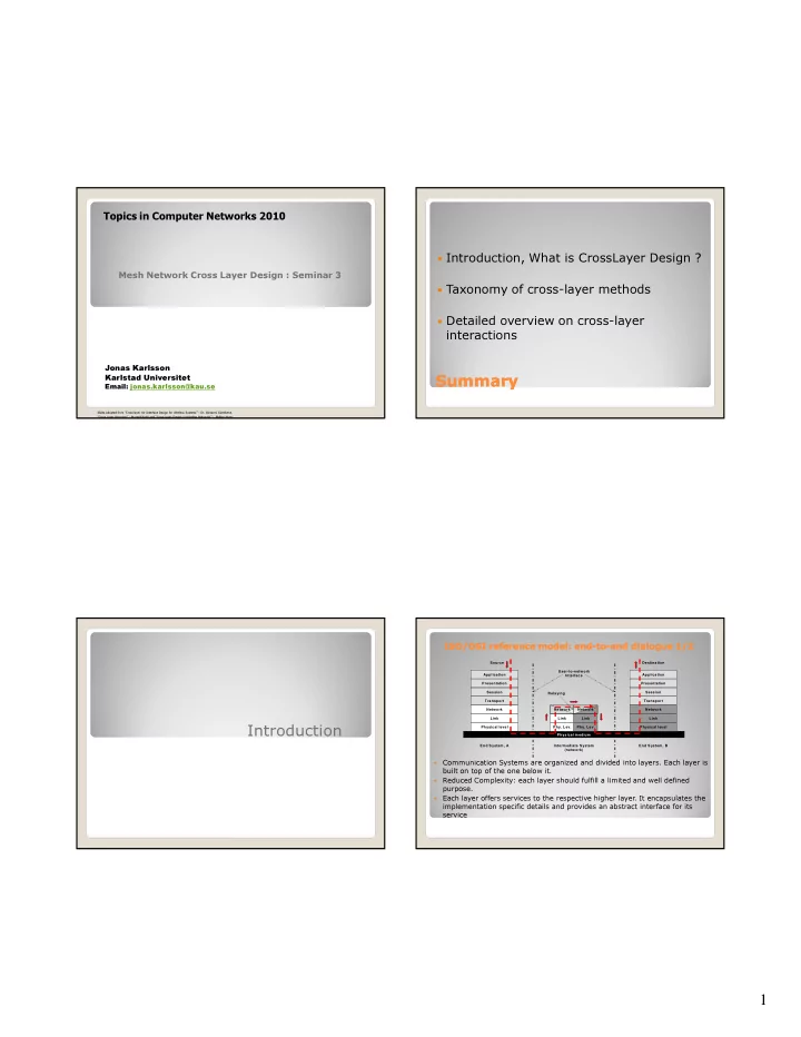
ISO/OSI reference model: end ISO/OSI reference model: end-
- to
to-
- end dialogue 1/2
end dialogue 1/2
- Communication Systems are organized and divided into layers. Each layer is
built on top of the one below it.
- Reduced Complexity: each layer should fulfill a limited and well defined
purpose.
- Each layer offers services to the respective higher layer. It encapsulates the
implementation specific details and provides an abstract interface for its service
Application Presentation Session Transport Network Link Physical level Physical medium End System, A Network Application Presentation Session Transport Network Link Physical level End System, B Intermediate System (network) User-to-network Interface Source Destination Link Link
- Phy. Lev.
- Phy. Lev.
Network Relaying