Young & Franklin Inc. Electric Gas Valves and Actuators - - PowerPoint PPT Presentation

young amp franklin inc electric gas valves and actuators
SMART_READER_LITE
LIVE PREVIEW

Young & Franklin Inc. Electric Gas Valves and Actuators - - PowerPoint PPT Presentation

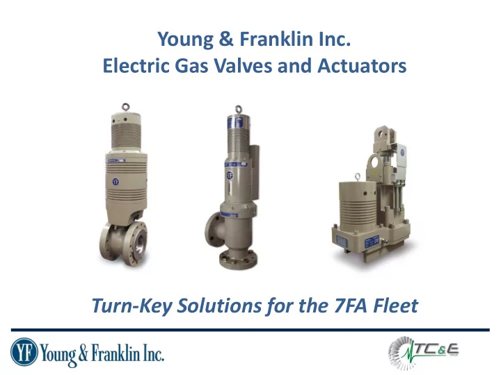
Young & Franklin Inc. Electric Gas Valves and Actuators Turn-Key Solutions for the 7FA Fleet Mission Statement Young & Franklin works with End-Users like you to reduce operations and maintenance costs by providing drop-in Electric


slide-1
SLIDE 1

Young & Franklin Inc. Electric Gas Valves and Actuators Turn-Key Solutions for the 7FA Fleet

slide-2
SLIDE 2

Mission Statement

– Young & Franklin works with End-Users like you to reduce

  • perations and maintenance costs by providing drop-in Electric

Gas Valves and Guide Vane Actuators

  • Each product meets or exceeds OEM requirements
  • YF’s EMA accept existing servo and trip commands eliminating command

logic changes to your control system

– 4-20mA command scheme also available

  • Qualified for 96,000 hour maintenance intervals significantly reduce
  • perating costs
  • Over 600 units installed worldwide

1

slide-3
SLIDE 3

Electric Stop/Ratio Valve

2

  • Fail Safe to closed position is accomplished by the use of two

torsion springs

  • Maximum 200ms trip time
  • Class VI V-Ball Valve with Composite Seat limits leakage due to

composite build-up

  • Class IV is available for heated fuel
  • The actuator is suitable for fuel modules in Class 1 Div 2

Hazardous Locations

  • V300 or SS-260 versions available
slide-4
SLIDE 4

3010 Gas Control Valve

3

  • Rated to 450oF gas temperatures
  • 10% better pressure recovery factor than legacy valves
  • Non-Plated valves eliminate downstream contamination
  • Fail Safe Spring to quickly close the valve
  • Maintenance/Service free actuator
slide-5
SLIDE 5

Inlet Guide Vane Actuator

4

  • Qualified to 40,000 lbf
  • Trip times within OEM specification
  • Various mounting & stroke options
  • Eliminates high pressure oil from

turbine compartment

slide-6
SLIDE 6

How do we get this done…. …… It’s easier than you think

5

slide-7
SLIDE 7

First Step, Justifying The Investment

  • Adding up the costs of maintaining your hydraulic system

– Typical Maintenance

  • Cost of stocking and replacing Servo’s & Filters
  • Cost and frequency of Overhauls

– Failures

  • Cost of failed parts
  • Cost of down time

– Environmental and Safety Issues

  • Cost of Insurance
  • Potential liability of oil leaks

– Commercial Issues

  • Capacity payments and fines

6

In 20 Minutes, Y&F Can Personalize Your Return On Investment

slide-8
SLIDE 8

Typical Return on Investment

7

slide-9
SLIDE 9

Next Step, Site Survey

8

Control System Questions 1 Exact model of turbine 2 What is the control system - MK5, 6, 6E, Ovation (picture is prefferable, with doors open) 3 Date of control upgrade, if applicable 4 Any plans for future updates 5 Command protocol - (4-20Ma OR -8 TO 8Ma) 6 Direction of positive and negative servo commands 7 Is customer interested: Enable Reset Fault 4-20 analog feedback 8 Does customer want to remove hydraulic system or cap 9 Is there independent lift oil DMC's Questions 1 Where will DMC's be mounted (picture of PEECC is preferrable) 2 How far from Batteries /Breaker 3 How far from Actuator GCV's/SRV Questions 1 Gas Temperature 2 P2 set point 3 Part numbers of exisiting valves 4 Orientation of valves 5 Fisher Ball Valve type 6 Is flow testing of valves required IGV Questions 1 Part Number of existing IGV (also need arrangement drawing) 2 Stroke 3 Bolted or Welded base 4 IGV Link Lengh (pin to pin) 5 Is a new link preferred 6 Side or Belly Mount

slide-10
SLIDE 10

Last Step, Installation

  • Determine Level of Support

– Full Mechanical and Electrical Installation available with TC&E

  • Pre-Outage

– Run electrical cables – Mount Digital Motor Controllers – Total Duration: 5 days

  • Mechanical installation

– Total Duration: 3 days

  • Calibration and Commissioning

– Total Duration: 1 day

9

slide-11
SLIDE 11

Diagnostic Capabilities Slow Ramp Current Test

10 0.00 2.00 4.00 6.00 8.00 10.00 12.00 14.00 0.00% 20.00% 40.00% 60.00% 80.00% 100.00%

Slow Ramp Current Draw P/N 3010E531-G001, S/N YF21037

Current Spike Corresponding To Wear Point

0.00 2.00 4.00 6.00 8.00 10.00 12.00 14.00 0.00% 20.00% 40.00% 60.00% 80.00% 100.00%

Slow Ramp Current Draw P/N 3010E531-G001, S/N YF22404

Factory Acceptance Test Test of Field Unit Test Gives Insight Into Health of the Actuator

slide-12
SLIDE 12

Diagnostic Capabilities Data Logging

11

  • The Data logger collects up to 100

samples/second for the following fields:

– Command (Up to 3 channels) – Position Feedback – Motor Current – Supply Voltage

  • Trends can be analyzed to monitor for

increased motor current

  • MODBUS output available for additional

data collection

slide-13
SLIDE 13

12

slide-14
SLIDE 14

13

www.yf.com 315-552-3250 www.tcexg.com 855-823-2875