
SLIDE 1
lecture 21 volume rendering
- blending N layers
- OpenGL fog (not on final exam)
- transfer functions
- rendering level surfaces
- 3D objects
Clouds, fire, smoke, fog, and dust are difficult to model with vertices and polygons. Volumetric models assume that light is emitted, absorbed, and scattered by a large number of particles.
- Visualization of 3D data
- medical imaging
- seismic data for oil and gas exporation
- distribution of temperature or density over a space
- ...
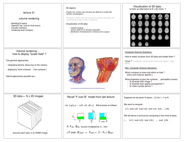
Visualization of 3D data:
Is there an alternative to N x 2D slices ?
Volume rendering -- how to display "scalar field" ?
Two general approaches:
- integrating density along rays to the camera
- displaying "level surfaces" ("iso-surfaces")
Hybrid approaches possible too...
http://www.cg.tuwien.ac.at/research/publications/2008/bruckner-2008-IIV/image-orig.jpg
Computer Science Questions: How to select surfaces from 3D data and render them ? Costs ? (Tradeoffs: computation time and space, user effort) Non- Computer Science Questions: Which surfaces to show and which to hide ? (class and instance specific ) What properties to give the surfaces... (perception issues)
- - to illustrate their shape ?
- to illustrate their spatial arrangement ?
- to make a pretty picture ?