SLIDE 1 ‘The Future of Quality Control for Wood & Wood Products’, 4-7th May 2010, Edinburgh The Final Conference of COST Action E53
http://cte.napier.ac.uk/e53
Validity of bending tests on strip-shaped specimens to derive bending strength and stiffness properties of cross-laminated solid timber (X-lam)
- R. Steiger 1 & A. Gülzow 2
Abstract The application of cross-laminated solid timber (CLT, X-lam) used as load- bearing plates requires information on the product’s strength properties; the design, however, is often governed by serviceability criterions. Hence, predicting the respective behaviour of such panels requires accurate information about their bending and shear strength as well as their elastic
- properties. Bending strength and stiffness of CLT have to be assessed following
the procedures in EN 789. The latter requires 4-point bending tests of strip- shaped specimens with a width of 300 mm, cut from the panels. By comparing results of bending tests on 100 mm and 300 mm wide strip-shaped specimens and on full panels it is shown, that neither MOR nor stiffness properties derived by testing single 100 mm wide strip-shaped specimens are appropriate to assess the respective properties of the original panels. However, with regard to stiffness properties, single 300 mm wide strips or samples of at least 5 to 6 100 mm wide strips lead to acceptable results. The analysis of the test data covers MOR, bending MOE parallel and perpendicular to the grain direction of the face layers as well as shear moduli. Rolling shear failures which frequently
- ccurred when testing the 100 mm wide strip-shaped specimens could not be
- bserved in destructive tests of gross CLT panels. It is concluded that tests on
single strip-shaped specimens should only be used in the course of quality control of CLT (i.e. to check sufficient adhesive bond of the layers) but not to derive mechanical properties of gross panels. 1 Introduction Cross-laminated solid timber (CLT) is assembled of cross-wise oriented layers
- f lamellas (mostly softwood). Compared to the raw material, CLT benefits from
homogenised mechanical properties. CLT is not only used as component of structural elements, but rather for load bearing plates and shear walls. In practice the design of plates loaded perpendicular to the plane is often governed by serviceability criterions like maximal deflection and vibration
- susceptibility. Appropriate verification of ultimate and serviceability limits of such
panels is only possible when relying on accurate information about the elastic properties as well as on the strength properties of the respective CLT product.
1 Senior Scientist, rene.steiger@empa.ch
Empa, Wood Laboratory, Dübendorf, Switzerland
2 Planning Engineer, guelzow@carbo-link.com
Carbo-Link GmbH, Fehraltorf, Switzerland
SLIDE 2 ‘The Future of Quality Control for Wood & Wood Products’, 4-7th May 2010, Edinburgh The Final Conference of COST Action E53
http://cte.napier.ac.uk/e53 The current European regulation EN 13986 (CEN 2004b) with regard to deriving the so-called “performance characteristics” bending strength (MOR) and bending stiffness (MOE, G) makes reference to the standard EN 789 (CEN 2004a). EN 789 requests 4-point bending tests of strip-shaped specimens with a width of 300 5 mm, cut from the CLT panels. The span has to be taken as 300 mm + 32 t, t being the nominal thickness of the CLT panel. The standard asks for only one specimen per plate and grain direction of the face layers to be tested respectively. The standard EN 13353 (CEN 2003b) being relevant for the requirements on CLT allows this respective test value to be taken as the mean value of the whole panel and for using this value for all statistical calculations where the mean value and the variation of the mean values of the panels are
- used. It is however said that “the variation within a panel and the according
calculations cannot be done” which means that e.g. characteristic values cannot be assigned to CLT based on the procedure described above. It is obvious that deriving mechanical properties from one single test is not reliable enough. However, in the course of production control such tests are useful to check e.g. sufficient quality of bond lines and can thus serve as a kind of “red light alert”. The question to what extent tests on strip-shaped specimens according to EN 789 are capable of reliably deriving MOR and bending stiffness of gross CLT panels was answered by an experimental campaign. 2 Material The study comprised of a total of 42 CLT panels with different lay-ups and geometrical dimensions as indicated in Table 1. The panels were supplied by two producers (A and B) and due to totally different ways of production the panels exhibited remarkable differences in appearance and mechanical properties although the raw material was in both cases visually strength graded Norway Spruce (Picea abies Karst.). Table 1: Geometrical properties of the investigated CLT panels Series Length 1) x Width [m] t [mm] Lay-up [mm] Sample size Product A and B: 10/50/10 9 x A, 9 x B 1 2.50 x 2.50 70 Product A and B: 25/20/25 9 x A, 9 x B Product A: 35/40/35 3 2.50 x 2.50 110 Product B: 20/70/20 3 Product A: 25/30/25 3 80 Product B: 15/50/15 3 Product B: 15/15/20/15/15 3 2 4.00 x 2.50 110 Product A: 35/40/35 3
1) parallel to the grain direction of the face layers
SLIDE 3
‘The Future of Quality Control for Wood & Wood Products’, 4-7th May 2010, Edinburgh The Final Conference of COST Action E53
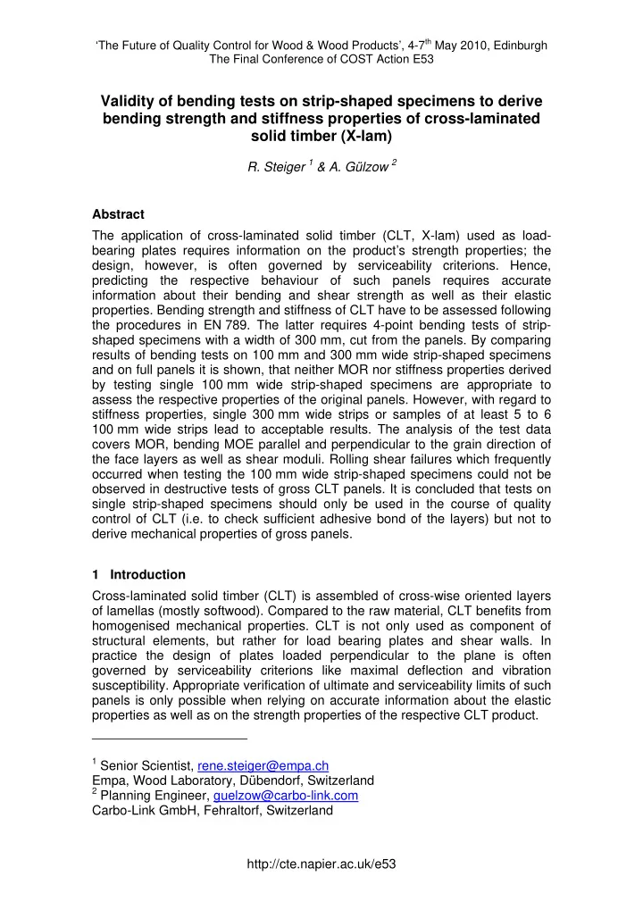
http://cte.napier.ac.uk/e53 Compared to product A, product B due to smaller sized components of the layers, lacking of grooves and due to bonding of the layers on all sides exhibits a higher degree of homogenization (Figure 1). Prior to testing in the lab, the panels as well as the strip-shaped specimens were stored in climatic chambers. The specimens reached and equilibrium moisture content of slightly below 12%.
Product A Product B Lay-up 10/50/10 mm Lay-up 25/20/25 mm
Figure 1: CLT products A (left) and B (right), t = 70 mm The scheme of cutting the strip-shaped specimens parallel and perpendicular to the grain direction of the face layers from the series 1 – CLT panels is shown in Figure 2 left. The width of the 5 – 6 strips per direction in series 1 was 100 mm. In the course of test series 2 two 300 mm wide strips (one per grain direction of the face layers) were cut from each panel according to Figure 2 right.
Series 1 – CLT panels Series 2 – CLT panels
Figure 2: Scheme of cutting strip-shaped specimens from CLT panels. The arrow sign indicates the grain direction of the face layers.
SLIDE 4
‘The Future of Quality Control for Wood & Wood Products’, 4-7th May 2010, Edinburgh The Final Conference of COST Action E53
http://cte.napier.ac.uk/e53 3 Method 3.1 Evaluation of elastic properties of the CLT panels To derive stiffness properties of gross CLT panels a method was applied which had recently been studied and further developed at the Swiss Federal Laboratories for Materials Testing and Research, Empa (Gülzow 2008). The method is non-destructive and bases on experimental and theoretical modal analysis (Steiger et al. 2008). The method was shown to be capable of deriving two MOE (E11, E22) and three shear moduli (G12, G13, G23) of CLT panels with different geometrical dimensions and lay-ups (Gülzow et al. 2008). The directions of the principal axis as used in this paper are shown in Figure 3. Figure 3: Principal axis in CLT as used in this paper 3.2 Bending tests of gross CLT panels The series 1 CLT panels were subjected to destructive bending tests, the panels being simply supported on their four edges. The tests were carried out with three different loading cases: a) 4 single loads in the centre point of the panels’ quadrants, b) 1 single load in the centre of the panel and c) 1 single load in the centre of one quadrant. Deformations, failure load and failure mode were recorded (Czaderski et al. 2007). The MOR was calculated with the compound theory taking all layers into account (Bodig et al. 1993, Blass et al. 2003). 3.3 Bending tests of strip-shaped specimens Along series 1, due to restrictions by the available testing machine the width of the specimens was only 100 mm (EN 789 would have required 300 mm!) and thus the span was reduced similarly. Specimens were subjected to 4-point bending tests with a span of 1100 mm and a distance between the loading points of 300 mm (Howald et al. 2006) and MOR and stiffness as well as failure mode were recorded. The reference loads to determine MOE were 10% and 40% of the assumed failure load and the deformations were measured between the loading points on the upper side of the specimens. Speed of the loading head was adjusted such that failure was reached after 300 120 seconds. In series 2 the MOE in bending and the shear modulus were evaluated according to EN 408 (CEN 2003a) with the specimens having dimensions as asked by EN 789. The shear moduli G (G13 and G23) and the MOE Em (E11 and E22) were determined by the variable span method from the apparent MOE
SLIDE 5 ‘The Future of Quality Control for Wood & Wood Products’, 4-7th May 2010, Edinburgh The Final Conference of COST Action E53
http://cte.napier.ac.uk/e53 Em,app for each test piece as indicated in EN 408. The deformations were measured for 10% and 40% of the supposed failure load and the speed of loading was such that each test cycle lasted 1 minute, which is slightly above the test duration asked by EN 408. Strips with grooves and cuts (aiming at reducing warping due to changing moisture) were tested twice with changing
- rientation of tension and compression side.
4 Results and discussion 4.1 MOR, MOE and failure modes of strips cut from the series 1-CLT panels Figure 4 shows a comparison of MOR recorded along bending tests of gross CLT panels (dimensions: 2.50 x 2.50 x 0.07 m, lay-ups 10/50/10 mm and 25/20/25 mm) and of respective values derived from strip-shaped specimens (1.20 x 0.10 x 0.07 m) cut from the panels parallel to the grain direction of the face layers (Figure 2, left).
.01 .1 1 5 10 20 30 50 70 80 90 95 99 99.9 99.99 Panel tests of product A (n = 12) Panel tests of product B (n = 12) Strip-shaped tests of product A (n = 70) Strip-shaped tests of product B (n = 78) 20 30 40 50 60 Bending strength f
m [N/mm 2]
[%] 70
Figure 4: Comparison of MOR derived from tests on gross CLT panels with lay- ups 10/50/10 mm and 25/20/25 mm and on strip-shaped specimens (width = 100 mm) cut from these panels according to Figure 2, left For both products MOR derived from tests on strip-shaped specimens is considerably lower than when performing bending tests on whole panels. Comparing the variation of results (represented by the slope of the linear regression lines) it can be seen that testing of strip-shaped specimens with a width of 100 mm is not capable to correctly account for the higher degree of homogenisation of product B, whereas this difference can clearly be seen when comparing the test results of the gross CLT panels. In the course of the strip
SLIDE 6 ‘The Future of Quality Control for Wood & Wood Products’, 4-7th May 2010, Edinburgh The Final Conference of COST Action E53
http://cte.napier.ac.uk/e53 tests in 4-point bending shear failures occurred frequently, whereas this was not the case with the gross CLT panels. There, due to comparably lower shear stresses, bending failure on the tension side was predominant. A shear failure was noticed in one single case only. However, once punching occurred. Figure 5 shows mean, maximum and minimum values of the MOE E11 and E22
- f 5 – 6 strips per panel and grain direction of the face layers. The high CoV
clearly indicate a large variation of the stiffness properties within single CLT panels independent of their lay-up. When comparing the mean values of the strip test samples to the respective values derived by modal analysis of the gross CLT panels, the biggest difference is 21% for strips tested parallel to the grain direction of the face layers (E11) and 14% perpendicular to it (E22). No clear trend of over- or underestimating could be found. In average (mean values
- f all strip-shaped specimens cut from the same panel) the differences are for
E11 10% (product A) and 6% (product B) and for E22 7% (product A) and 8% (product B). When plotting all series of the CLT panels with lay-up 10/50/10 in normal probability plots (NPP) (Figure 6) it can be seen that the mean values of the MOE of the strip tests are marginally higher than the ones derived by modal analysis of the gross panels. Comparing the slopes of the linear regression lines in the NPP, again much bigger variability of the strip test samples is obvious. Overall variations are higher in product A than in product B which can be explained by a different degree of homogenization due to the different ways of production and the quality of the raw material (see 2). This phenomenon, however, is marked more for MOE E11 and E22 of the gross panels than for the strip test samples. 4.2 MOE and shear moduli of strips cut from the series 2 -CLT panels Generally MOE and shear moduli could be derived with high accuracy by the variable span method (CEN 2003a). However, some single values in the test series with strips oriented perpendicular to the grain direction of the face layers did not fit the trend line well, this being due to opening of layers at lamella contacts which were not glued together. When such zones in specimens tested at large span are placed in the middle of the spans, the openings take much more influence on the test results than when being put near the supports in tests with short spans. Consequently respective test results were excluded from
- analysis. Figure 7 shows a comparison of MOE (E11, E22) and shear moduli
(G13, G23) derived by modal analysis of the gross series-2 CLT panels and by bending tests of strip-shaped specimens cut from the respective panels according to Fig. 2, right. The diagonal line in the figure indicates the ideal case, where parameters derived by modal analysis would be equal to those derived by static bending tests of the strip-shaped specimens. The results are grouped by type of product and geometrical parameters of the panel as indicated in Table 1 and in the caption of the figure. The differences independent from type
- f product are small to moderate. Parameter E22 even shows a very good
- agreement. Some big differences are visible between values derived on gross
panels and on strip-shaped specimens respectively especially regarding the MOE E11 and the shear moduli G13 and G23.
SLIDE 7 ‘The Future of Quality Control for Wood & Wood Products’, 4-7th May 2010, Edinburgh The Final Conference of COST Action E53
http://cte.napier.ac.uk/e53
E11 - Panels of lay up 10/50/10 5000 10000 15000 A1 A2 A3 A7 A8 A9 A10 A11 A12 B13 B14 B15 B19 B20 B21 B22 B23 B24 Panel E11 [N/mm 2] 2 4 6 8 10 12 14 16 18 20 CoV [%] E11, modal analysis, whole panel E11, strips, mean values E11, strips, maximum values E11, strips, minimum values COV . Product A Product B E22 - Panels of lay up 10/50/10 5000 10000 A1 A2 A3 A7 A8 A9 A10 A11 A12 B13 B14 B15 B19 B20 B21 B22 B23 B24 Panel E22 [N/mm 2] 5 10 15 20 25 30 35 CoV [%] E22, modal analysis, whole panel E22, strips, mean values E22, strips, maximum values E22, strips, minimum values COV Product A Product B
E11 - Panels of lay up 25/20/25 5000 10000 15000 A4 A5 A6 B16 B17 B18 Panel E11 [N/mm
2]
2 4 6 8 10 12 14 16 18 CoV [%] E11, modal analysis, whole panel E11, strips, mean values E11, strips, maximum values E11, strips, minimum values COV Product A Product B
E22 - Panels of lay up 25/20/25 500 1000 A4 A5 A6 B16 B17 B18 Panel E22 [N/mm2] 2 4 6 8 10 12 14 16 18 CoV [%] E22, modal analysis, whole panel E22, strips, mean values E22, strips, maximum values E22, strips, minimum values COV
Figure 5: MOE E11, E22 derived by 4-point bending tests of 100 mm wide strip- shaped specimens (5 – 6 specimens per series 1-CLT panel) or by modal analysis of gross panels (x-signs) together with respective coefficients of variation (CoV)
SLIDE 8 ‘The Future of Quality Control for Wood & Wood Products’, 4-7th May 2010, Edinburgh The Final Conference of COST Action E53
http://cte.napier.ac.uk/e53
.01 .1 1 5 10 20 30 50 70 80 90 95 99 99.9 99.99 E11-Product A-Panels E11-Product B-Panels E11-Product A-Strip-shaped specimnes E11-Product B-Strip-shaped specimnes 5000 10000 15000 MOE [N/mm
2]
[%] .01 .1 1 5 10 20 30 50 70 80 90 95 99 99.9 99.99 E22-Product A-Panels E22-Product B-Panels E22-Product A-Strip-shaped specimens E22-Product B-Strip-shaped specimens 1000 2000 3000 4000 5000 6000 7000 8000 MOE [N/mm2] [%]
Figure 6: NPP of MOE E11 and E22 derived by 4-point bending tests of 100 mm wide strip-shaped specimens (5 6 specimens per series 1-CLT panel) and by modal analysis of gross panels (lay-up 10/50/10 mm only) A closer look on the specimens turned out, that big differences mainly resulted from striking non-homogeneities in the used raw material. Since specimens with marked cuts and grooves were tested twice with changing orientation of the tension side in bending, it could be concluded that the test procedure did not systematically affect the data. Differences between values derived by modal analysis and by static testing, however, also result from the well-known fact that stiffness parameters derived by means of dynamic methods due to the high speed of action are approximately 6% higher than those determined on base of static experiments at comparably lower loading rate (Görlacher 1984).
SLIDE 9 ‘The Future of Quality Control for Wood & Wood Products’, 4-7th May 2010, Edinburgh The Final Conference of COST Action E53
http://cte.napier.ac.uk/e53
E 11
2000 4000 6000 8000 10000 12000 14000 16000 2000 4000 6000 8000 10000 12000 14000 16000 E 11 from modal analysis [N/mm2] E11 from static test of strip [N/mm2]
Q_0.11_3L_A R_0.11_3L_A R_0.08_3L_A Q_0.11_3L_B R_0.08_3L_B R_0.08_5L_B
E 22
500 1000 1500 2000 2500 3000 3500 4000 4500 500 1000 1500 2000 2500 3000 3500 4000 4500 E 22 from modal analysis [N/mm2] E22 from static test of strip [N/mm2]
Q_0.11_3L_A R_0.11_3L_A R_0.08_3L_A Q_0.11_3L_B R_0.08_3L_B R_0.08_5L_B
G 13
50 100 150 200 250 50 100 150 200 250 G 13 from modal analysis [N/mm2] G13 from static test of strip [N/mm2]
Q_0.11_3L_A R_0.11_3L_A R_0.08_3L_A Q_0.11_3L_B R_0.08_3L_B R_0.08_5L_B
G 23
200 400 600 800 1000 200 400 600 800 1000 G 23 from modal analysis [N/mm2] G23 from static test of strip [N/mm2]
Q_0.11_3L_A R_0.11_3L_A R_0.08_3L_A Q_0.11_3L_B R_0.08_3L_B R_0.08_5L_B
Figure 7: Comparison of MOE and shear moduli derived by modal analysis of the gross CLT panels and by bending tests of single strip-shaped specimens cut from the respective panel according to Fig. 2, right. (Labels: Q/R = quadric/rectangular panel 2.50 x 2.50 m / 4.00 x 2.50 m, 0.11/0.08 = panel thickness [m], 3L/5L = 3/5 layers, A/B = Product) 5 Summary and conclusions Strength properties can be assigned to CLT by means of the compound theory. However, the mechanical properties (strength and stiffness) of the layers have to be known which means that the raw material has to be strength graded. Deriving stiffness properties of whole CLT panels with modal analysis is a good alternative to estimating them on base of the mechanical properties of the single layers by means of the compound theory. Especially in cases where the raw material is not strength graded or its mechanical properties are not known with sufficient precision, the modal analysis can help in assigning correct stiffness properties to CLT.
SLIDE 10 ‘The Future of Quality Control for Wood & Wood Products’, 4-7th May 2010, Edinburgh The Final Conference of COST Action E53
http://cte.napier.ac.uk/e53 After having proven the correctness of the modal analysis method by static proof loading, the panel properties were compared to bending MOE and shear moduli derived from tests on strip-shaped specimens cut from the CLT panels. One part of the tests additionally focused on bending strength and failure
- modes. From the tests the following conclusions could be drawn:
Bending strength and stiffness of CLT panels can vary quite strongly within
- ne single panel. For both parameters differences in strength and stiffness
- f strip-shaped specimens cut from the panels of up to 100% have been
- found. Hence it is not possible to derive strength and stiffness properties of
CLT panels from bending tests of few or single strip-shaped specimens. The accuracy of the test results when performing bending tests of strip- shaped specimens according to EN 789 is increased with increasing sample
- size. Mean values of at least 5 – 6 specimens better describe the actual
bending stiffness of the panels. Average differences in MOE then amount to 10% (E11) and 6% (E22) but can still reach 20%. The variation of the stiffness properties depends on the degree of homogenisation of the actual CLT product. The smaller the components (lamellas) are and the less the variation in mechanical properties is (due to e.g. a strength grading of the raw material), the better it can be concluded from tests on strip-shaped specimens to the bending strength and stiffness properties of the gross CLT panel. Compared to gross CLT panels, local non-homogeneities and faults (knots, pitch pockets, deviated grain, not adhesively bonded contacts, grooves, cracks) take more influence on the mechanical properties of the strip-shaped
- specimens. The smaller the width of such specimens is, the more their load-
bearing behaviour is affected by local defects and non-homogeneities due to the quality of the raw material or due to the way of producing the panels. The distances between middle layer parts not adhesively bonded at their edges and the number of grooves, which are aimed at reducing the deformations of the CLT panel in case of changing moisture, take a big influence on the shear moduli. When deriving respective values on base of testing strip-shaped specimens this possible variation has to be taken into account by using empirical relationships. When testing strip-shaped specimens in 4-point bending, (rolling) shear failures occur quite frequently, whereas such failure modes could not be
- bserved when testing gross CLT panels to failure in loading situations
- ccurring in practice. There bending failure was dominating. Punching,
however, should be regarded, especially with thin panels and products with grooves and layers not adhesively bonded at their edges. Single tests on strip-shaped specimens may serve as an instrument of production control especially regarding the quality of bonding. They should, however not be used to derive mechanical properties of CLT panels. In scientific studies testing of strip-shaped specimens should only be carried
- ut on big samples. Geometrical dimensions should not be taken smaller
than asked by the standards and generalization of conclusions in most cases is not possible (e.g. type of failure).
SLIDE 11
‘The Future of Quality Control for Wood & Wood Products’, 4-7th May 2010, Edinburgh The Final Conference of COST Action E53
http://cte.napier.ac.uk/e53 Acknowledgments The study was financially supported by the Swiss Federal Office for Professional Education and Technology OPET (Innovation Promotion Agency CTI) and by the Swiss Federal Office for the Environment FOEN (Wald- und Holzforschungsfonds WHFF). The test specimens were supplied by Pius Schuler AG, CH-6418 Rothenturm, Switzerland (www.pius-schuler.ch) and by Schilliger Holz AG, Haltikon 33, CH-6403 Küssnacht (www.schilliger.ch). References Blass, H. J. & Görlacher, R. (2003) "Bemessung im Holzbau: Brettsperrholz – Berechnungsgrundlagen". Holzbau-Kalender, pp 580-598. Bruderverlag, Karlsruhe, Germany. Bodig, J. & Jayne, B. A. (1993) "Mechanics of wood and wood composites". Krieger Publishing Company, Malabar, Florida, USA. CEN (2003a) "EN 408: Timber structures - Structural timber and glued laminated timber - Determination of some physical and mechanical properties, European Committee for Standardization. CEN (2003b) "EN 13353: Solid wood panels (SWP) - Requirements, European Committee for Standardization. CEN (2004a) "EN 789: Timber structures - Test methods - Determination of mechanical properties of wood based panels", European Committee for Standardization. CEN (2004b) "EN 13986: Wood-based panels for use in construction - Characteristics, evaluation of conformity and marking, European Committee for Standardization. Czaderski, C., Steiger, R., Howald, M., Olia, S., Gülzow, A. & Niemz, P. (2007) "Versuche und Berechnungen an allseitig gelagerten 3-schichtigen Brettsperrholzplatten". Holz als Roh- und Werkstoff, Vol 65, pp 383-402. Görlacher, R. (1984) "Ein neues Messverfahren zur Bestimmung des Elastizitätsmoduls von Holz". Holz als Roh- und Werkstoff, Vol 42, pp 219-222. Gülzow, A. (2008) "Zerstörungsfreie Bestimmung der Biegesteifigkeiten von Brettsperrholzplatten". PhD Thesis Nr. 17944, ETH Zürich, Switzerland. Gülzow, A., Gsell, D. & Steiger, R. (2008) "Zerstörungsfreie Bestimmung elastischer Eigenschaften quadratischer 3-schichtiger Brettsperrholzplatten mit symmetrischem Aufbau". Holz als Roh- und Werkstoff Vol 66, pp 19-37. Howald, M. & Niemz, P. (2006) "Massivholzplatten für das Bauwesen – Be- richtsteil I/1: Berechnungsmodell für Massivholzplatten - Ermittlung mechani- scher Eigenschaften anhand von Ultraschall-Messungen und Biegeversuchen an Kleinproben". Institut für Baustoffe, ETH Zürich, Switzerland. Steiger, R., Gülzow, A. & Gsell, D. (2008) "Non-destructive evaluation of elastic material properties of cross-laminated timber". Proceedings of COST E53 Conference on "End user's needs for wood material and products". 29th – 30th October 2008, Delft, The Netherlands, pp 171-182.