DAMAGES IN THERMOPLASTIC COMPOSITE STRUCTURES: APPLICATION TO HIGH - - PDF document

damages in thermoplastic composite structures application
SMART_READER_LITE
LIVE PREVIEW

DAMAGES IN THERMOPLASTIC COMPOSITE STRUCTURES: APPLICATION TO HIGH - - PDF document

18 TH INTERNATIONAL CONFERENCE ON COMPOSITE MATERIALS DAMAGES IN THERMOPLASTIC COMPOSITE STRUCTURES: APPLICATION TO HIGH PRESSURE HYDROGEN STORAGE VESSELS C.Thomas1*, F.Nony 1 , S.Villalonga 1 , J.Renard 2 1 CEA, DAM, Le Ripault-F-37260 Monts,


slide-1
SLIDE 1

18TH INTERNATIONAL CONFERENCE ON COMPOSITE MATERIALS

1 Introduction For several years, CEA has been involved in the development of type IV high pressure vessels and has obtained promising achievements [1]. This type

  • f vessels presents an hydrogen proof polymeric

liner reinforced by a structural composite layer. Up to now, the design of this structural layer takes classically into account the material/components initial mechanical properties and safety coefficients but without any consideration of durability and damage tolerance. This study focuses on the different damages

  • ccurring in carbon fibres / polyamide matrix

composite structures with the

  • bjective

to understand their influence on mechanical properties and then on the conception and manufacturing processes of composite structures. Thus, a first part is dedicated to the characterization of the material and particularly its initial thermal and mechanical properties. Then, considering the different

  • rientations
  • f

the filament-wound structure, damage processes are investigated (matrix cracking, delamination, fiber breaks) under quasi-static or fatigue loading. In addition, first results of dedicated filament winding process are presented. The influence of key parameters is also assessed. 2 Initial mechanical properties of materials 2.1 Material and samples manufacturing The materials studied are polyamide matrices (polyamide 6 and 12) reinforced with T 700 Carbon fibers from Toray SOFICAR : Carbostamp TM PA 6 and Carbostamp TM PA 12. The fiber volume fraction is about 50% (value determined by pyrolysis at 500°C). The test samples are manufactured by hot compression moulding [2]. The material and the mould are heated to reach a temperature above the melting temperature of the matrix. Then a pressure is

  • applied. Finally, the mould is cooled still under

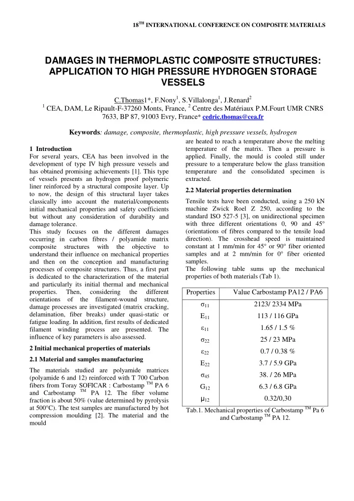
pressure to a temperature below the glass transition temperature and the consolidated specimen is extracted. 2.2 Material properties determination Tensile tests have been conducted, using a 250 kN machine Zwick Roel Z 250, according to the standard ISO 527-5 [3], on unidirectional specimen with three different orientations 0, 90 and 45° (orientations of fibres compared to the tensile load direction). The crosshead speed is maintained constant at 1 mm/min for 45° or 90° fiber oriented samples and at 2 mm/min for 0° fiber oriented samples. The following table sums up the mechanical properties of both materials (Tab 1).

Properties Value Carbostamp PA12 / PA6 σ11 E11 ε11 σ22 ε22 E22 σ45 G12 12 2123/ 2334 MPa 113 / 116 GPa 1.65 / 1.5 % 25 / 23 MPa 0.7 / 0.38 % 3.7 / 5.9 GPa

  • 38. / 26 MPa

6.3 / 6.8 GPa 0.32/0,30

Tab.1. Mechanical properties of Carbostamp TM Pa 6 and Carbostamp TM PA 12.

DAMAGES IN THERMOPLASTIC COMPOSITE STRUCTURES: APPLICATION TO HIGH PRESSURE HYDROGEN STORAGE VESSELS

C.Thomas1*, F.Nony1, S.Villalonga1, J.Renard2

1 CEA, DAM, Le Ripault-F-37260 Monts, France, 2 Centre des Matériaux P.M.Fourt UMR CNRS

7633, BP 87, 91003 Evry, France* cedric.thomas@cea.fr Keywords: damage, composite, thermoplastic, high pressure vessels, hydrogen

slide-2
SLIDE 2

The behaviour of both material can be considered as linear elastic for 0 and 90° directions, whereas in 45° direction the behaviour is non linear. This non linear behaviour can be directly linked to the visco plastic behaviour of the matrix. The visco plasticity can be shown by loading/unloading test performed on

  • samples. A hysteresis loop and a residual plastic

strain can be noticed with stress increasing (Fig. 1).

  • Fig. 1 Loading/unloading tensile test on [458]

samples For 90° fiber oriented samples, the value of stress at break are lower than matrices one (55 MPa for PA 12 and 65 MPa for PA 6). Thus, fiber/matrix interfaces show weak strength in spite of the presence of matrix transcrystalline phase on the fiber surface [4]. 3 Study of damage processes of carbon fiber / polyamide matrix composite 3.1 Damage by transverse cracking under tensile loading Basically, tensile tests on UD specimens produced no cracking and failure occurring with no prior macroscopic warning. Cross-plied laminates such as stacking sequences of [02, 904, 02] exhibit matrix cracking when they were submitted to tensile loading [5]. The cracks appear parallel to the fibers in plies oriented off the loading direction (plies at 90° in this case). The loading is applied by 50 MPa steps until break. The number of cracks is evaluated at the end of every loading/unloading cycle. The evolution of the density of cracks (i.e. the number of cracks per observed length expressed in mm) as a function of applied load show the kinetic of damage by intralaminar cracking (Fig.2). As it can be seen, the material presents a Kaiser effect, since the damage density of the cycle n+1 increases if the loading stress is up to the cycle n one. For both materials no crack was observed for an applied stress below 200 MPa (Fig. 3). Above this level, the level of crack density increased until a limit which seems to be reached before failure, at around 600

  • MPa. For an applied load up to 700 MPa,

longitudinal cracks and delaminating appear until break (Fig. 4 and 5). Fig.2. Crack density evolution with applied stress for [02, 902]s sequences of Carbostamp TM PA 12 et PA 6

  • Fig. 3

Transverse cracks (200 MPa < σ < 600 MPa)

  • Fig. 4.

Longitudinal cracks (σ > 700 MPa)

  • Fig. 5.

Delaminatin g (σ > 700 MPa) It can be observed that the limit of crack density of Carbostamp TM PA 6 is lower than Carbostamp TM PA 12 one. That can be explained by the strength of the matrix which is higher for PA 6. Moreover, numerical simulations show that, in the 90° oriented plies, the level for which another crack appears is higher for Carbostamp TM PA 6. 3.2 Damage by transverse cracking and delaminating under shear load This damage process is studied on [±45]s laminates submitted to loading/unloading tensile load by 10

slide-3
SLIDE 3

3

MPa increasing steps. This sequence show a similar behaviour than [458] sequence. First of all, this behaviour can be considered as non linear. Then, for an applied stress up to 25-30 MPa, the formation of a hysteresis loop can be noticed. This loop is wider and wider with the increasing stress. In addition to that, the material presents a residual plastic strain. This residual strain is directly linked not only to the visco plasticity of the matrix but also to damages that appear in the plies. First, transverse cracks appear for an applied load ranging from 10 to 40

  • MPa. Then, when the load is up to 40 MPa,

delaminating are developing at the cracks

  • extremities. The damages spread and grow through

the sample until its break. These damages influence the shear rigidity of the

  • material. This influence can be revealed through the

evolution of shear modulus, G12, as a function of applied load. The shear modulus decreases while the applied load increases. The influence of two parameters on this evolution has been assessed. Three different loading rates (0.1, 1 and 5 MPa/s) and three different relaxation times (2, 15 and 30 minutes) have been tested. One can see in Fig. 5 and 6 that these two parameters have no influence on the evolution of shear modulus and thus on the damage process. Fig.5. Influence of the loading rate on the evolution

  • f the shear modulus (a) Carbostamp TM PA 12, (b)

Carbostamp TM PA 6 Fig.6. Influence of the relaxation time on the evolution of the shear modulus (a) Carbostamp TM PA 12, (b) Carbostamp TM PA 6 However, these two parameters have an influence on the residual strain. Indeed, the residual strain increases when the loading rate decreases, since the creep phenomenon is more important. Besides, this residual strain decreases when the relaxation time

  • increases. One can see this observation for

CarbostampTM PA 6 on Fig. 7.

  • Fig. 7. Influence of the loading rate (a) and the

relaxation time (b) on the residual strain during loading/ unloading tests performed on [±45]s Carbosatmp PA 6 laminates

The results of fatigue tests are consistent with those obtained during previous loading / unloading one. The values of number of fatigue cycles at failure are given in Tab. 2 for both materials and different values of σmax.

For a maximum stress varying from 0.5 σbreak to 0.7 σbreak, CarbostampTM PA 6 appears with a weaker fatigue strength. Indeed, it shows a lower fatigue life (number of cycles at failure) than CarbostampTM PA 12, and, the decrease of shear modulus is higher and faster. This difference in fatigue behaviour is explained by the brittle of PA 6 matrix, unlike PA 12, which is ductile. For a maximum stress equal to 0.4 σbreak, both materials become tough and have similar behaviours.

0,4 σbreak 0,5 σbreak 0,6 σbreak 0,7 σbreak CarbostampTM PA12 > 10 000 > 10 000 7 300 4 600 CarbostampTM PA 6 >10 000 4 900 2 750 460

  • Tab. 2. Fatigue life of CarbostampTM PA 6 and PA

12 ([±45]s, 1 cycle/min, σmax=0.4 σbreak, 0.5 σbreak, 0.6 σbreak, 0.7 σbreak)

slide-4
SLIDE 4

Fig.8. Evolution of shear modulus with number of fatigue cycles for Carbostamp TM PA 6 and PA 12 3.3 Damage by fiber break Damage processes by fiber breaks depends on the statistic law of fiber failure properties. 40 failure tensile tests have been conducted until break on fibers meshes (24 000 fibers per mesh). A Weibull [6] statistical law has been established and gives the evolution of failure probability function of applied stress (Fig. 9 and equation 1). Figure 9. Fiber probability of failure with applied stress

m

e P

r ) (

1

σ σ −

− =

(1) With m=24,82 and σ0 = 4097 MPa The kinetic is followed by acoustic emission (Fig. 13).Three different stages can be considered. The first one corresponds to the failure of weaker fibers. Before this step, there is no emission. Then, breaks appear near the broken fibers with the increase of the

  • stress. Indeed, the probability to break a fiber is

higher when the stress increases. It corresponds to an exponential evolution of acoustic activity. The last stage corresponds to the failure of the sample.

  • Fig. 10. Acoustic emission evolution and fiber

breaks observation for a UD sample submitted to tensile load 4 Manufacturing by filament winding and influence of processing parameters 4.1 Manufacturing process description The composite structural layer of vessels is manufactured by filament winding. The main difficulty is the high flexural rigidity of the semi

  • product. Heating of the tape is thus required for two

main reasons. The first reason is to soften the entire matrix to allow a relative motion of the tape in the wound configuration. The second one consists in heating the surface layer of the matrix to a temperature above the melting point Tm, for adequate molecular inter diffusion between the layer being wound and those already wound. Adequate heating should lead to appropriate bounding. Different heating systems can be found such as hot gas, infrared, laser, ultrasonic, microwave. Most of the process developed present a preheater (infrared radiators or hot gas tubes), which raises the temperature just below the melting and an end- heater (gas torches, infrared radiators or laser heating), near the mandrel, which raises it above the melting temperature [7]. Many parameters can have an influence on the material structure and properties [8, 9, and 10]. The heating temperature must be high enough to reach the viscosity value which makes the matrix inter diffusion easier. Yet, it must not trigger matrix oxidation or thermal degradation. Finally, a

slide-5
SLIDE 5

5

pressure must be applied to ensure satisfying

  • consolidation. This pressure must be high enough to

minimize void content. The prepreg is also subjected to a roving tension, which must not be appropriate to avoid broken

  • filaments. The velocity of the mandrel plays also a

key role. It must not be too high to allow the consolidation to be efficient and to avoid the breaking of reinforcing fibers. For this study, a process dedicated to the manufacturing of both pipes and vessels is being developed (Fig. 11). A cylindrical aluminium mandrel is used for rings and pipes manufacturing whereas, for vessels manufacturing, the composite layer is directly wound on the polymeric liner. Firstly, the tape spool is submitted to an adjustable tension thanks to magnetic brakes, which allow adjusting the force required. Then, the tape is driven by rollers to a pre heating system (infrared short wave radiators) .A first IR thermometer measures the temperature at the end of the pre-heating system, and the power of the radiator is adjusted taking into account this measurement. At the nip-point, before the contact with the mandrel, the composite layer is heated above its melting temperature by two others infrared shortwave radiators. The temperature of the incoming tape is also controlled by an IR

  • thermometer. For consolidation of the incoming tape

with the layer already placed onto the mandrel, a compaction roller is used. The pressure is ensured thanks to a pneumatically control system.

  • Fig. 11. Filament winding process dedicated to

polyamide / carbon fiber composites 4.2 Influence of key parameters on structure and properties For this study, two parameters (velocity and heating temperature) are kept constant. The influence of roving tension and consolidation pressure is evaluated on rings manufactured by filament

  • winding. Fiber volume fraction, density and void

content are measured. Mechanical properties are determined by tensile tests performed according to the standard ASTM D 2290 [11]. This testing method is easy to conduct but the stress distribution is inhomogeneous along the perimeter of the ring. The stress concentration is particularly high in the area of the gap. The young modulus is not

evaluated.

The fiber volume fraction is not influenced by both parameters, unlike void content and tensile strength. When the consolidation pressure increases, the void content decreases, whereas the tensile stress at break

  • increases. The pressure improve the matrix inter

layer diffusion. Thus, the adhesion between the layers is enhanced like the load transfer. Concerning the roving tension, when it increases, the void content decreases. Like the consolidation pressure, the roving tension improves the structure

  • consolidation. In addition to that, it allows keeping

the fiber orientation. Thus, the tensile stress at break increases. Fig.12. Influence of consolidation pressure on mechanical properties and void content

slide-6
SLIDE 6

Fig.13. Influence of roving tension on mechanical properties and void content 5 Conclusion and prospects Type-IV 70 MPa technology already meets hydrogen permeation, cycling and burst

  • requirements. On going development are focusing
  • n cost reduction and durability improvement. In

that way, thermoplastic matrix / carbon fibers composites, more precisely polyamide matrix one have been identified as relevant candidates. Up to now, the determination of initial mechanical properties has shown the behaviour of the two materials in different loading directions. It can be noticed that the fiber / matrix interface strength is weak. A filament winding process dedicated to polyamide (6 or 12) / carbon fibers composites has been developed and the influence of key parameters has been assessed. High level of roving tension and consolidation pressure are required to ensure good structure consolidation. Vessels will be manufactured with the best compromise

  • f

parameters. In parallel, study on damage processes, like transverse cracking, delaminating or fiber breaks are

  • done. The kinetic of damage and the limits are
  • determined. The two materials exhibit closed
  • behaviour. This study aims at understanding the

material behaviour under damage and at taking it into account for the design and the manufacture of the composite layer. The final stage of the study will be the characterization of vessel manufactured according to the optimized design. Acknowledgement This work has been supported by the French National Research Agency through Plan d’Action sur l’Hydrogène et les Piles à Combustible (Project HYPE, N°ANR-07-PANH-006). References

[1] F. Nony and al. “Type IV 700 bar-vessel for compressed gaseous hydrogen storage: material research and performance achievements”. Proceedings of Conference 17th World Hydrogen Energy Conference, Brisbane, Australia, 2008. [2] P. MC Donnell, K.P. Mc Garvey, “Processing and mechanical properties evaluation of a commingled carbon-fibre/PA 12 composite”, Composites: Part A, 32, pp. 925-932, 2001 [3] NF EN ISO 527-5, « Détermination des propriétés en traction, conditions d’essai pour les composites plastiques renforcés de fibres unidirectionnelles », juillet 1997 [4] M. Evstatiev, K. Friedrich., S. Fakirov, “Crystallinity Effect on Fracture Rings made of Thermoplastic Powder impregnated Carbon

  • r

Glass Fiber Composites”, International Journal of Polymeric Material, 21, pp 177-187, 1993 [5] J. Renard, J.P. Favre, T. Jeggy. “Influence of transverse cracking o, ply behaviour: introduction of a characteristic damage variable”, Composite Science and Technology, 46, pp. 29-37, 1993 [6] W. Weibull, “ A statistical distribution function of wide applicability “, Journal of Applied Mechanics,

  • Vol. 9, pp. 293-296, 1951

[7] J.A.H.M. Buijs, P.J. Nederveen, “A study of consolidation in filament winding with thermoplastic prepregs”, Journal of Thermoplastic Composite Material, Vol. 5, pp. 276-286, 1992 [8] F. Henninger, K. Friedrich, “Thermoplastic filament winding with online impregnation. Part A: process technology and operating efficiency”, Composites: Part A, 33, pp. 1479-1486, 2002 [9] F. Henninger, K. Friedrich, “Thermoplastic filament winding with

  • nline

impregnation. Part B: Experimental study of processing parameters”, Composites: Part A, 33, pp. 1677-1688, 2002 [10] B.Lauke, A. Schöne, K. Friedrich, “High performance thermoplastic composites fabricated by filament winding”, Proc.

  • f

International Confrerence on Advanced Composites, Wolongong, Australia, 1993 [11] Standard ASTM D 2290, « Standard Test Method for Apparent Hoop Tensile Strength of Plastic or Reinforced Plastic Pipe by Split Disk Method », 2004