Underground nuclear waste storage Groundwater flow and radionuclide - - PowerPoint PPT Presentation

underground nuclear waste storage
SMART_READER_LITE
LIVE PREVIEW

Underground nuclear waste storage Groundwater flow and radionuclide - - PowerPoint PPT Presentation

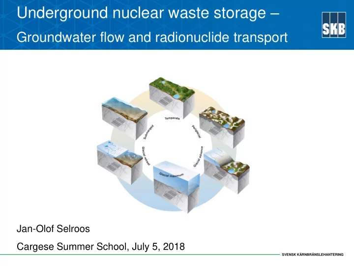
Underground nuclear waste storage Groundwater flow and radionuclide transport Jan-Olof Selroos Cargese Summer School, July 5, 2018 SVENSK KRNBRNSLEHANTERING Contents: Concept for geological disposal of nuclear waste A few words


slide-1
SLIDE 1

SVENSK KÄRNBRÄNSLEHANTERING

Jan-Olof Selroos Cargese Summer School, July 5, 2018

Underground nuclear waste storage –

Groundwater flow and radionuclide transport

slide-2
SLIDE 2

SVENSK KÄRNBRÄNSLEHANTERING

  • Concept for geological disposal of nuclear waste
  • A few words on Performance/Safety Assessments
  • Hydrogeological modelling in support of geological disposal of nuclear

waste

  • Site-descriptive understanding
  • Safety assessment applications
  • Examples
  • Conditioning of DFN models
  • The ENIGMA experiment at Äspö HRL
  • Conclusions

Contents:

slide-3
SLIDE 3

SVENSK KÄRNBRÄNSLEHANTERING

Concept for geological disposal of nuclear waste – the SKB example

Nuclear power plants Low- and intermediate- level waste Health care, industry and research Transportation by m/s Sigrid High-level waste Final Repository for Short-lived Radioactive Waste Interim Storage Facility for Spent Nuclear Fuel with planned encapsulation facility Final Repository for Spent Nuclear Fuel

slide-4
SLIDE 4

SVENSK KÄRNBRÄNSLEHANTERING

SKB’s method

Concept for geological disposal of nuclear waste – the SKB example

Fuel pellet of uranium dioxide Spent nuclear fuel Nodular iron insert Bentonite clay Surface part of final repository Cladding tube Fuel assembly of BWR type Copper canister Crystalline bedrock Underground part of final repository

approx. 500 m

slide-5
SLIDE 5

SVENSK KÄRNBRÄNSLEHANTERING

Assessment of consequences

DOI 10.1007/s13280-013-0395-5

slide-6
SLIDE 6

SVENSK KÄRNBRÄNSLEHANTERING

Assessment methodology – SKB SR-Site

slide-7
SLIDE 7

SVENSK KÄRNBRÄNSLEHANTERING

Linking groundwayter flow and radionuclide transport simulations

DOI 10.1007/s10040-012-0888-5 Groundwater flow Nearfield RN transport Farfield RN transport

slide-8
SLIDE 8

SVENSK KÄRNBRÄNSLEHANTERING

Radionuclide transport

slide-9
SLIDE 9

SVENSK KÄRNBRÄNSLEHANTERING

Final risk estimate SR-Site (TR-11-01)

slide-10
SLIDE 10

SVENSK KÄRNBRÄNSLEHANTERING

Site-descriptive modelling and Performance/Safety asessment modelling

slide-11
SLIDE 11

SVENSK KÄRNBRÄNSLEHANTERING

Site investigations

slide-12
SLIDE 12

SVENSK KÄRNBRÄNSLEHANTERING

  • Surface investigations
  • Airborne photography and surface geophysical investigations
  • Lithological mapping and mapping of structural characteristics
  • Investigations of Quaternary deposits
  • Meteorological and hydrological monitoring, hydrochemical sampling
  • f precipitation, surface waters and shallow groundwater
  • Drilling and borehole measurements
  • 25 (Forsmark) and 43 (Laxemar) deep (800 - 1,000 m) cored drilled

boreholes

  • Several more shallow core drilled and percussion drilled boreholes
  • Mapping, testing and monitoring boreholes and bore cores
  • Many soil/rock boreholes through Quaternary deposits

Surface-based site investigations

slide-13
SLIDE 13

SVENSK KÄRNBRÄNSLEHANTERING

Site-descriptive modelling

slide-14
SLIDE 14

SVENSK KÄRNBRÄNSLEHANTERING

Site-descriptive modelling

slide-15
SLIDE 15

SVENSK KÄRNBRÄNSLEHANTERING

Site-descriptive modelling

slide-16
SLIDE 16

SVENSK KÄRNBRÄNSLEHANTERING

  • A site descriptive model integrates

various types of data from field investigations and associated laboratory studies in a single, coherent, logical and defensible description of a site.

  • The site descriptive model not
  • nly provides specialized

information and data needed to support safety assessment and engineering studies, but also provides complementary evidence to support a safety case.

Site-descriptive modelling

slide-17
SLIDE 17

SVENSK KÄRNBRÄNSLEHANTERING

Groundwater leakage into open tunnels How does inflow of water affect construction and operations? How can inflow be minimized? Environmental Impact Assessment How are lakes and wetlands above the repository affected during construction and

  • perations?

Groundwater flow and chemistry How will groundwater at repository depth affect the technical barriers? Transport of radionuclides In case of canister breach, how are radionuclides transported through the gesophere to the biosphere?

Modeling of construction,

  • perations and safety after closure
slide-18
SLIDE 18

SVENSK KÄRNBRÄNSLEHANTERING

The Safety Assessment SR-Site

slide-19
SLIDE 19

SVENSK KÄRNBRÄNSLEHANTERING

Embedding of models/concepts

slide-20
SLIDE 20

SVENSK KÄRNBRÄNSLEHANTERING

Temperate climate conditions:

  • Saturation of backfill
  • Hydrogeological and hydrogeochemical development
  • Recharge and discharge locations
  • Performance measures (Darcy flux, equivalent flow rate, flow-related

transport resistance, advective travel time)

  • Penetration of dilute water
  • Effect of engineering imperfections (EDZ, crown space, spalling)
  • Site-descriptive model-based variants (uncertainty)
  • Unsealed boreholes and other what-if analyses

Typical hydrogeological issues in PA/SA

slide-21
SLIDE 21

SVENSK KÄRNBRÄNSLEHANTERING

Example results: Discharge as a function

  • f time
slide-22
SLIDE 22

SVENSK KÄRNBRÄNSLEHANTERING

Example results: Darcy flux at deposition holes

slide-23
SLIDE 23

SVENSK KÄRNBRÄNSLEHANTERING

Glacial/periglacial climate conditions:

  • Advancing ice sheet (glaciation)
  • Different ice sheet movement/speed
  • Different types of periglacial conditions
  • Different permeability conditions

(permafrost, hydro-mechanical effect)

  • Maximum ice sheet coverage
  • Retreating ice sheet (deglaciation)

Typical hydrogeological issues in PA/SA

slide-24
SLIDE 24

SVENSK KÄRNBRÄNSLEHANTERING

Example results: Darcy flux at deposition holes

slide-25
SLIDE 25

SVENSK KÄRNBRÄNSLEHANTERING

  • Main radiological risks are associated

with the erosion-corrosion (both flow- related) and shear load scenarios.

  • If (large) flowing fractures can be

avoided in deposition hole positions and deposition tunnels, risk is dramatically reduced.

  • Two-fold objective:
  • To increase determinism in description of

fracture intersections with deposition holes (geometry and flow).

  • To have correct distribution of flow in

deposition holes within full repository.

Conditioning of DFN models – the deterministic-stochastic transition

slide-26
SLIDE 26

SVENSK KÄRNBRÄNSLEHANTERING

  • Fracture traces: Fracture orientations

can be matched. Size still unknown!

  • Hydraulic data (hydraulic

signatures) provide information

  • n network characteristics.

Conditioning - data sources and issues

slide-27
SLIDE 27

SVENSK KÄRNBRÄNSLEHANTERING

  • To evaluate the performance we need common test- or benchmark

cases: a Hypothetical Site

  • Perfectly known geology (geometries, properties, trends and ”recipe”)
  • Controlled samples (all intersections can be traced to a unique fracture)
  • Nested models (allows realistic resolution of samples)

Use of a Synthetic reality

r0 = 10 m r0 = 1m r0 = 0.1 r0 = 0.038 m

slide-28
SLIDE 28

SVENSK KÄRNBRÄNSLEHANTERING

  • In unconditional

simulation, fractures not matching traces removed.

  • A library of fractures pre-

calculated; a matching fracture picked from library and placed in position where trace found.

  • Also hydraulic criteria can

be applied when choosing fracture from library.

Conditioning approach

slide-29
SLIDE 29

SVENSK KÄRNBRÄNSLEHANTERING

Unconditional vs conditional simulation of specific capacity (”transmissivity”) vs synthetic true value

Results of conditioning

slide-30
SLIDE 30

SVENSK KÄRNBRÄNSLEHANTERING

  • Conditioning creates models

honoring reality in higher degree concerning location of deposition holes with flowing fractures.

  • Important if different conditions

prevail for different parts of repository (e.g. recharge/discharge)

  • Conditional simulations

exhibit less stochastic variability in Darcy flux (U) and Flow-related transport resistance (F) than unconditional simulations.

  • Less uncertainty in predictions
  • f radiological risk!

Safety assessment implications

Mean difference in log(U) or log(F) for flowing holes between observed and conditioned data, based on conditioning in pilot holes for deposition holes

slide-31
SLIDE 31

SVENSK KÄRNBRÄNSLEHANTERING

  • Will combined hydraulic-tracer-

geophysical (GPR) data provide additional constraining power (conditioning data) on the fracture network characteristics in the vicinity of deposition holes?

  • ENIGMA PhD project: Flow and transport

in fracture networks: reducing uncertainty

  • f DFN models by conditioning to

geology and geophysical data (GPR)

  • Develop and test a general framework to

condition discrete fracture network (DFN) models to geological mapping and geophysical data in order to reduce the uncertainty of fractured rock properties and flow patterns

The ENIGMA experiment at Äspö HRL

slide-32
SLIDE 32

SVENSK KÄRNBRÄNSLEHANTERING

Direction of the end

  • f the tunnel

ENIGMA – preliminary GPR results

slide-33
SLIDE 33

SVENSK KÄRNBRÄNSLEHANTERING

ENIGMA – suggested boreholes for experiments

Tests to be performed: Push-Pull/SWIW tests Convergent dipole test + surface-based GPR

slide-34
SLIDE 34

SVENSK KÄRNBRÄNSLEHANTERING

  • Groundwater flow and radionuclide transport modelling are central parts
  • f the integrated Performance/Safety asessment.
  • Groundwater flow and chemistry affects performance of engineered

barriers, and also transports radionuclides through the geosphere to the biosphere in case of breached containment.

  • Fractured crystalline rock can only be described in a stochastic sense

due to natural variability.

  • Conditioning can increase determinism, and hence help in avoiding

unsuitable deposition locations.

  • The ENIGMA project at Äspö HRL tests novel combined measurement

and modelling techniques to improve the conditioning capability.

Some conclusions